PCB: how to eat
The theme of beginners in printmaking, young artists.
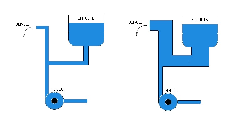
Here's two pictures, vividly drawn water, the water is pumped up by the pump, there is a capacitance (capacitor) and the output (load, for example a leg of the power supply of the microcontroller, the chip power supply, amplifier — does not matter):

The output is very important that the water flow was stable, but the pump is very naughty and the water can at the entrance for a short time to disappear. The same output may rapidly require more water than can provide the pump. The picture on the left the stability of the stream more difficult to organize, due to the thin diameter of the pipe between capacity and output. On the right, the output stability is aged better due to lower resistance capacity output.
Of course you can complain to the scheme, for example, the location of the pump, pressure water pump and container, let them be equal.
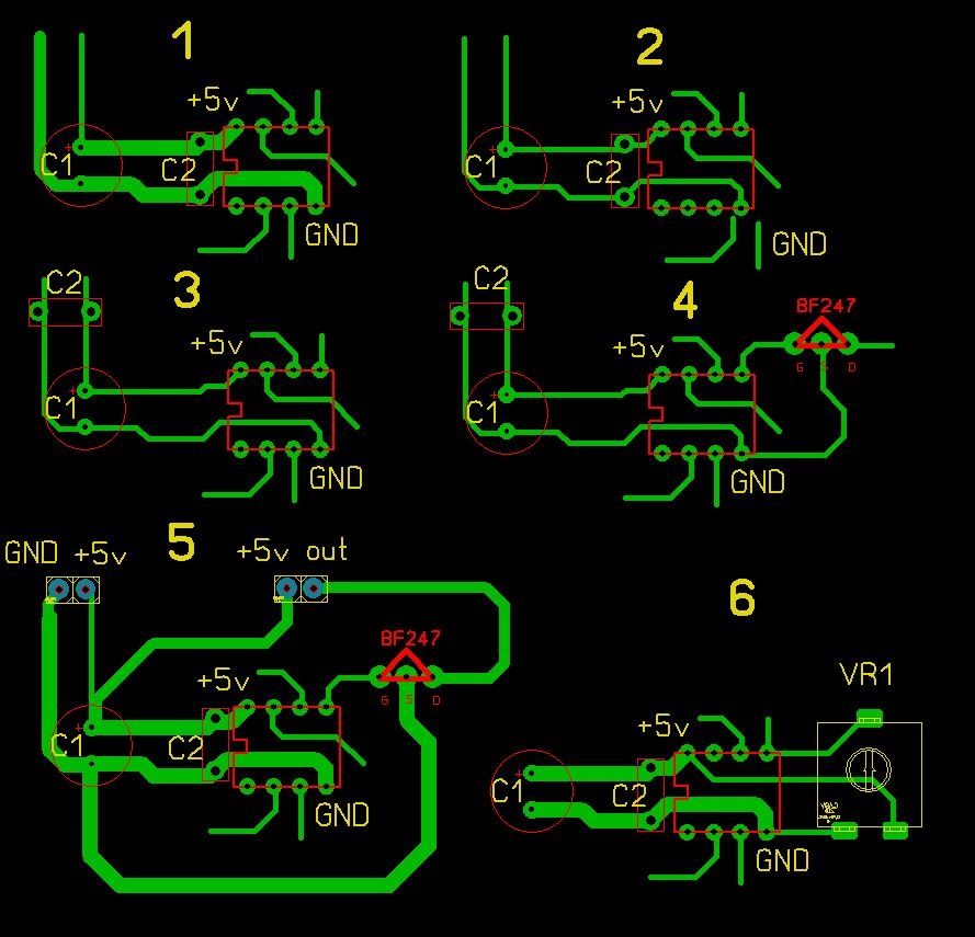
Now to printed boards, six samples of examples of schemes:

Once the warning scheme is conditional, not real life, we need the concept of the principle, do not use specific names of chips and denominations.
1 a circuit. Correct. There are electrolytic capacitor — capacity. There is a ceramic capacitor C2 is located as close as possible to the legs power the microcontroller.
2. Not very correct. The capacitor C2 is close, but tracks fine and have great resistance. In the real world the incorrectness of the circuit under big question, because the thickness of all the tracks and so thick, and the distance is very short. But for the concept — go. Who do not understand: assume that the microcontroller and the lamp eats the amps.
3. scheme. In General, incorrect. The capacitor C2 is located God knows where.
4. scheme. Wrong. The output power is connected to the transistor, for example, manages a powerful enough load. Between the plot of S2-S1-GND of microcontroller when enabled, the transistor will drop voltage that is bad for the stability of the microcontroller.
5. the scheme is correct. The power circuit of the load connected to the source with a lower internal resistance, to electrolytic capacitor C1.
6. scheme. Example of connecting the trimmer to the ADC simple microcontroller, provided that the analog ground AGND and digital GND are one and the reference voltage source of either the internal or the power bus.
Spider84
+1.
100n before the controller and he will be happy. Right now looked at the STM32 maximum nagruzke with all all all 200mA. So he has 6 pairs of legs.
And Yes, this is IMHO a matter of course to do typing thicker. But the percent applicable is weak.
if percent would be those roads, the fronts would be very long )
Unfortunately today, manufacturers of automotive electronics is widely used three-layer Board, and basely driven a lot with power in the inner layer!((
Given the sharp fronts and soft feeds may also be relevant. In General, this approach is rather a reflex of good manners. Ie unbreakable habit)
And often really helps this design, when picking something big and someone else's undocumented — a couple of hints. Especially comfortable when the width of nutritious different paths (with their multiplicity) — a look then he vytseplyat land and food.
+1.
100n before the controller and he will be happy. Right now looked at the STM32 maximum nagruzke with all all all 200mA. So he has 6 pairs of legs.
And Yes, this is IMHO a matter of course to do typing thicker. But the percent applicable is weak.
And the meaning of the microcontroller, which eats 20 mA, to make such a track? To force it clear, but the MC need filtrik or conder at least that would protect against interference with the load.
Yes, physics, but the laws on spatial imagination necessary to endure. You must know the inductance of conductors, mutual capacitance, the direction and strength of current in the conductors, common wire (ground), for example, to Keep in mind elements with a large current consumption pulse consumption, the items with low internal resistance, a circuit with high resistance. To visualize the electric field around the conductors, etc.
In the end, it turns out that designing is an art. And teach the art, and the laws of physics, unfortunately. And not all get this to acquire.
KIRR-electronic
Physics, nothing more.
Physics-physics, but there are some different sense should be. When bred microwave Board — that is definitely art... And pulse devices, and differenzialnye pair on the Board...
The right thing. I would like to add: the thickness of the tracks is a controversial matter, and depends on protegemos current, in the General case, of course the thicker the better, but depends on the situation — in the dinning schemes fat track a pretty good catch interference. As well very good to observe the rule — the power goes from one leg to the other component, i.e. for example from the diode to the leg of one capacitor, then to the leg of another capacitor and then for example to the conclusion of MK. And that glitches were not — on each leg of power chip ceramic 100n.
Yes, I'm the same wanted to tell. In General, it would be better if the pump by a separate pipe into the tank will be the water pump.
Note: on the first picture, the right half. The pump should move to the right to the vessel and from junction to lead output, otherwise the picture is not quite right...
At work for weeks redraw fees, so that the Feng Shui was all about, why is it necessary for the "blinking led". And Yes, I agree with you)
Silevrn
And does it make sense to bother with a proper breeding if we are talking about a microcontroller? Something I think the game not worth the candle, and another thing when it's something precision, low noise.
It is necessary to do always :) Perfection has no limits!
And does it make sense to bother with a proper breeding if we are talking about a microcontroller? Something I think the game not worth the candle, and another thing when it's something precision, low noise.
All right. By the way if to solder SMD-shku, conduc almost to the leg slapped.
And generally really it is necessary to consider power lines and signal. Somewhere the signal is output to the side screens and put.
I messed around once with a homemade umzch, and the result was good, but now do other stuff. But as they say, the former does not happen!
Handsome. I add a little bit. For umzch collected on the IP and any other analog IP to minimize low-frequency noise in the PCB layout used several lands, which are combined in a star point, and it power down negative supply. For digital IC critical time constant of signal propagation (complex magnitude depending on the resistance, mutual inductance and capacitance of the tracks relative to the earth) signal on the roads, and on diet only need to filter the noise.
interesting observation, when working with microwave if the track turns at right angles, with sharp right angles of the track, the signal it may not pass )))
Personally, in practice, faced with such nuances in the layout of printed circuit boards:
1 — with the reference generators in automotive amplifiers (from 40kHz) when tracks have sharp rough shape sooner and more appear all sorts of spurious interference with rectangular pulses especially at the front and a little less on the decline of the pulse, with increase in the frequency of the waveform may obezobrazit beyond recognition. When the PCB layout using the rounded shape tracks with a smooth transition from thin to thick and, if necessary, on the contrary — signal distortion lower.
2 — circuit-Board amps since the mid 80s the Japanese liked to introduce the distinction between fees for units and to delineate their ground, a thick carpet which was surrounded by a separate part of the Board but not all were connected in a ring and closed as if to itself via 0.1 UF
Question why do you need 2 capacitors to use ? And when it is better to use electrolytic and ceramic capacitors ?
Electrolyte large capacitance smoothes the ripple and sags in voltage.
A ceramic or tantalum to filter high frequency interference from fuckin impulsnykh, navedeni HF and so forth.
The electrolyte should not be taken too large, since the supply voltage circuit of the power point-the condenser may be too much current and can burn the road.
The electrolyte has a high capacity and can extinguish a large distortion, but the low frequency. Ceramic capacitor a lot smaller in capacity, but quietly digesting high frequency, from which the electrolyte boil.
Question why do you need 2 capacitors to use ? And when it is better to use electrolytic and ceramic capacitors ?
Which program is faster and easier to draw a diagram? Preferably the program easier.
yeah. everywhere has its own nuances. compare electric current with water flow is the best option at the Institute convinced. good article.