Integrated device Opel Vectra A
This device to my car has nothing to do. Rather the scheme of the device is the same but an order to the Opel Vectra A. PP Which will be installed in the car Moskvich 2141.
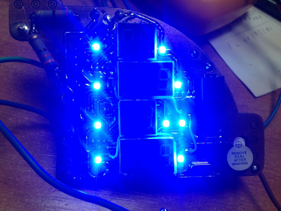
Time spent a lot, but the PCB layout was done about 3 days but it was worth it. And the result I want to share. The task to place the indicators in the already existing template. The simplest would be to just solder the LEDs and wires to bring everything for her in some box and not steamed. But if this version that fails to understand then it is very difficult. in the second to give petruha with hundreds of wires and say then he will understand when you put is also wrong. So I decided to make a single charge, which only bring the wires for the sensors. I got it, special thanks to the customer for the patience =).
A little load of photos and then video review
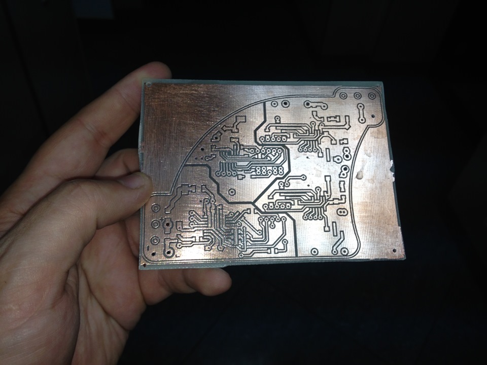
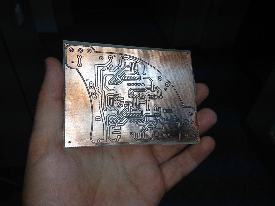 That's the price of the device will resemble bilateral
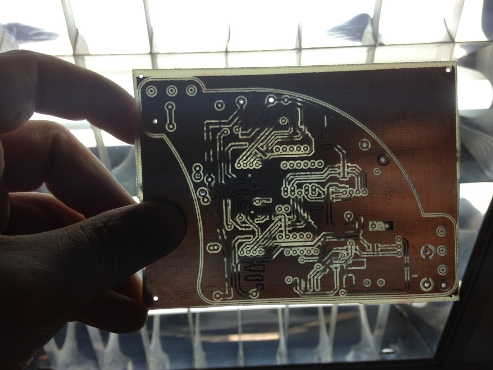
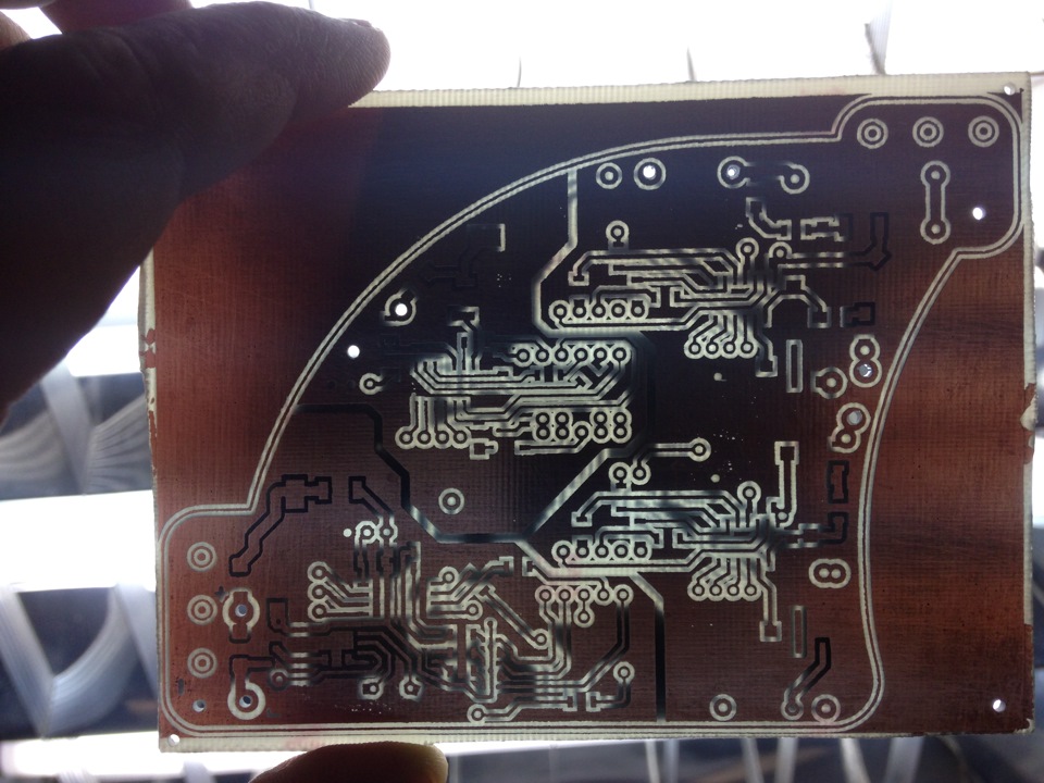 And tracks a few dozen times moving from one side to another in the lumen is clearly visible.
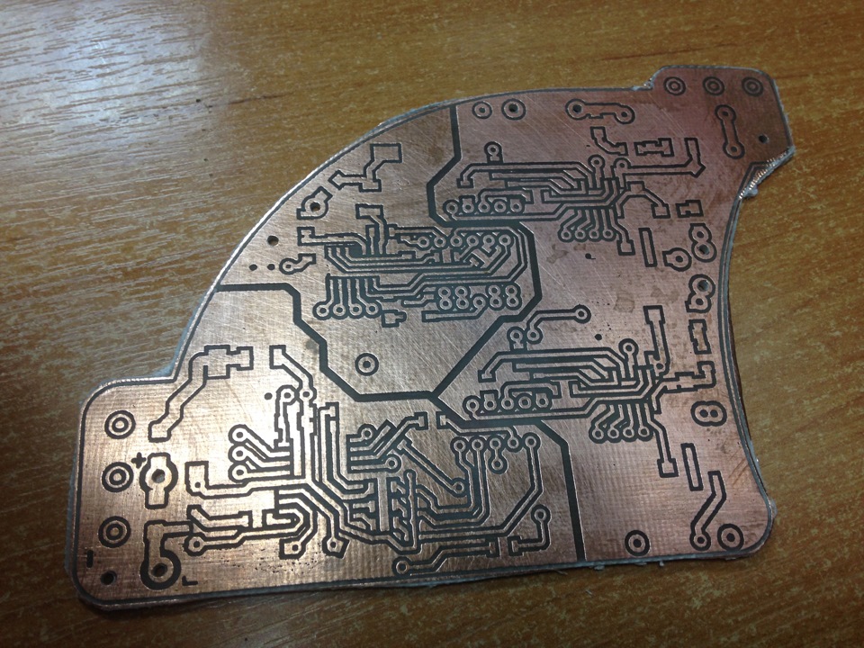
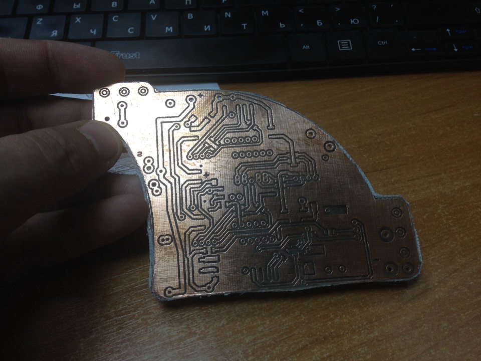 One more important thing is the mounting of components
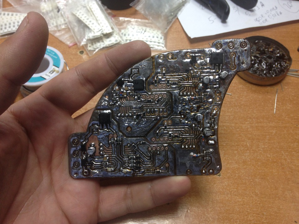 If on the back no problems, then on the front you need to solder all MOSFETs and transistors. hiding under the LEDs and mounting after soldering the indicators is not possible.
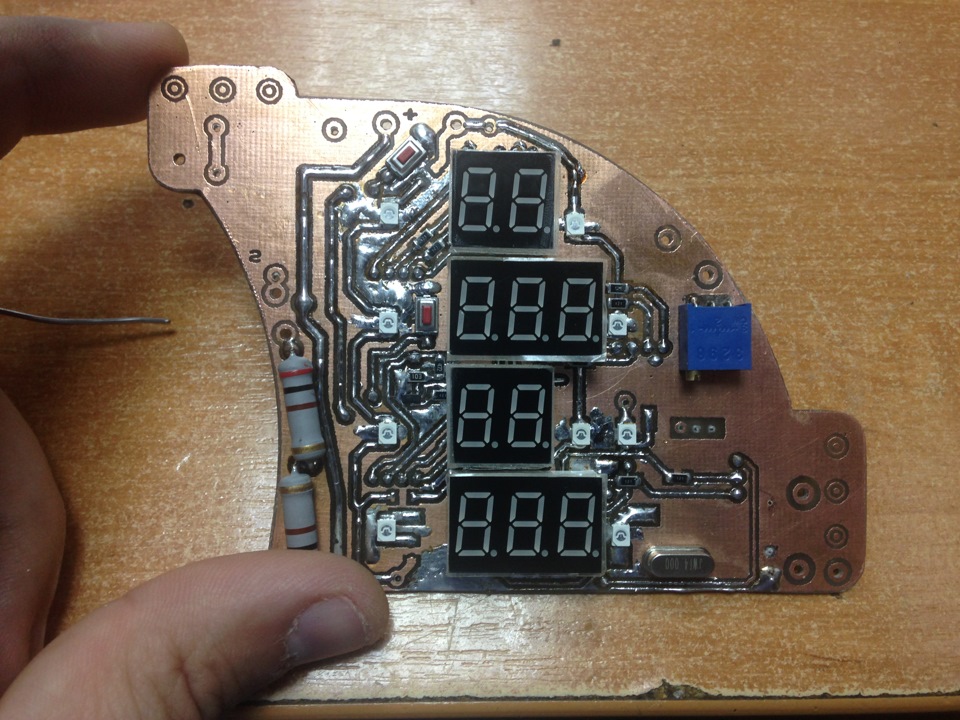 Setting of indicators also has a strict sequence. So as to not contaminate and will not reinvent the wheel indicators are set from the bottom to the top. Moreover, depending on the wiring and the legs of the indicator or it passes through the charge (classical mount) and surface mount with a bent leg up or to the side of the indicator.
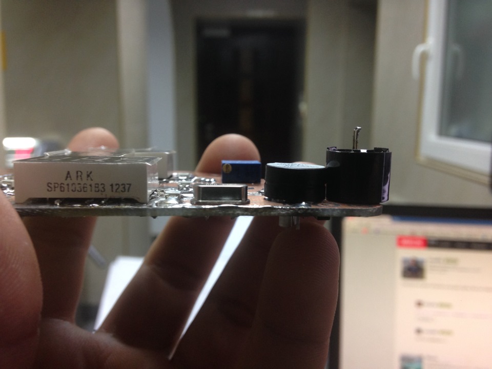 Had to find and reduced the thickness of the sound emitter in place of the usual 10 mm is 6 mm but of their existence I knew from past projects.
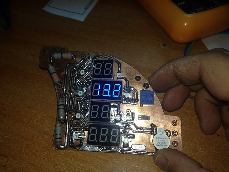
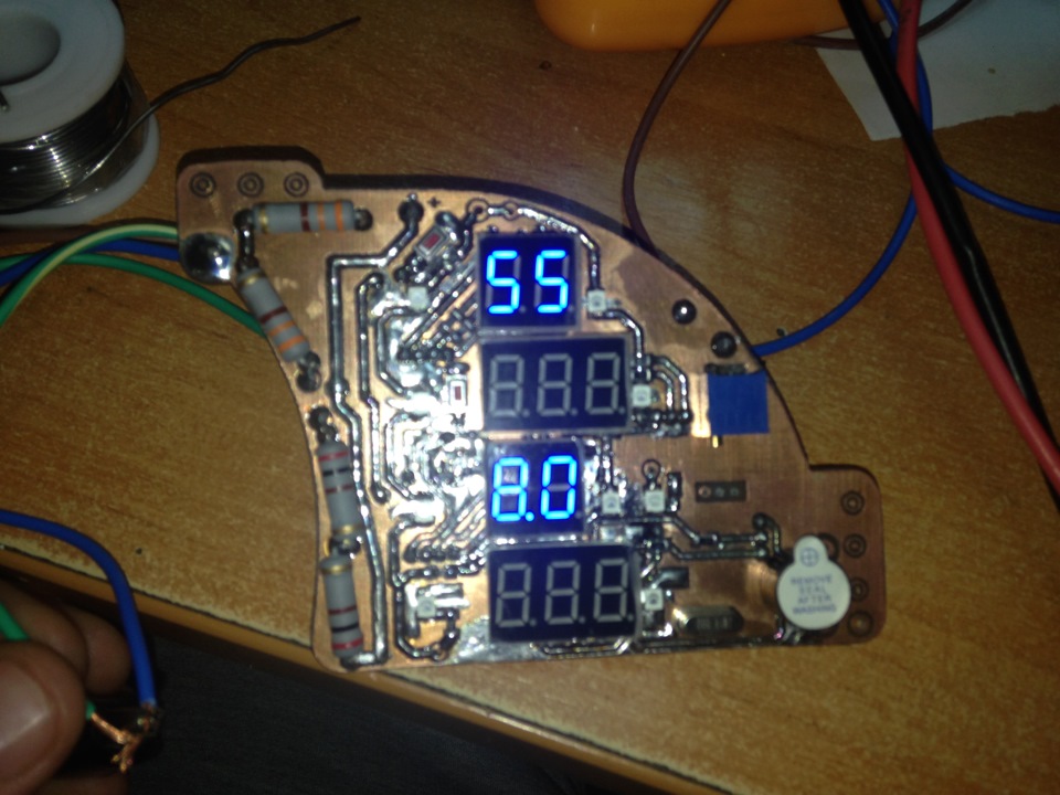
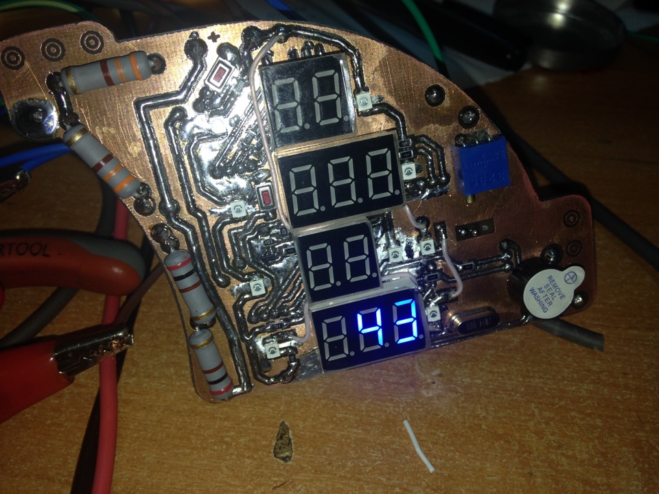 And then alternately run all the devices individually.
On the Board there are still 3 jumper wire of MGTF but they can only be used in the backlight because the diodes are connected by chains 3 PCs and then to feed + to the backlight.
 Another caveat is that the devices despite the fact that they are on the same Board have a separate power supply as + and ground. The backlight also has a separate +12V and ground from that, I have encountered already in their tidy, most of the schemes for the dimer lighting, smooth ignition and extinction are managed for minus. In order not to bind the customer to any lighting scheme is not in contact with the circuit devices.
Well, according to tradition, after the "mnogabukav" video work devices
Thank you master, see you soon...
I think where you need more patience to breed a double-sided Board or cross stitching a picture 1х1м
I found at the time as the father of charge painted with nail Polish. the truth of the question about tracks of 0.5-0.8 mm did not exist. Drawing pen on a leaf in the cage then minted the point on the PCB and connected them according to leaf. BJ is the method described in the first records, flood is of course a very simplified life
Just remembered how at the time when there was no technology LUT had to make 100 plat for 200 holes each. Manually it was necessary to dissolve the seal and then raspadura to draw the wiring followed by etching and mounting.
As I then searched for such drill, was not found. The trick is that the drill is flexible just the tip was carbide. Now only the chinks are starting to do
Drill my father bought in the Czech Republic then. Them for long enough he drilled Emily :-))))
I've duct-taped the paper in the cage to the PCB, drilled the holes, then cleaned the burrs with emery and draw on the holes nitrocellulose lacquer seal. Then I was lucky that I bought a drill with a carbide tip which began to sit in the one hundredth Board
Night in the "ball pressure"? Caught myself thinking that even MUFON night annoying =)) (maybe it's just my "quirks")
But not for that)) Just the work is so delicate and the jewelry that I was even on this Board (to breed) and even should not dream =))
A dimmer switch in this device have? Lit indicators are muted?
need to discuss details. tomorrow I will send an example (picture) what you want.
cool it! and tidy GAZ 3110 similar can be done (instead of the drain of the voltmeter)?
Also all counts in the unit time run 1 segment already checked red yellow 220 Ohm. Green blue 110 Ohms. The only resistors on the segments. The cathodes and not the anodes then the glow will be the same segments. Is from 1 to 4 digits In my practice, the maximum Svornosti which works steadily 14 on the generator at 8 MHz. When the duty ratio of 14 resistors 82 Ohm for red. But every book: the works for 4 seconds per minute in total. But this is an optical illusion. Camera take attenuation
the current through the 1 segment in the display 10-20 mA, there's also the usual led, i.e. 1 char = 7х20мА=140mA
But it's all right for static display, if the dynamics are there all the pulses and be considered differently.
pnpe
Most likely in the common cathode/anode LEDs.4 indicator 4 resistor.2 types of indicators 2 value of resistors.
Nonsense, the current through the indicator of 10-20 mA
Well, that's what I thought. Then why? Can all be done beautifully using a dynamic display.
Mono-Uchi
Well, it is clear that the power in the circuit ... what are they worth?
Most likely in the common cathode/anode LEDs.4 indicator 4 resistor.2 types of indicators 2 value of resistors.
I'm not aggressive. Not only for the two devices. Resistors are sequentially, again to increase efficiency and reduce heat. Yes, there are already 4 of the microcontroller. All independent just on the same Board
Yes well you're so aggressive?
Ie current resistors for 4 sensors, approx.
I thought that for indicators.
And who controls the indicators? There is certainly a controller is.
Device class motalok. But the color of indicators is not ice, although the masses bought and basically it.
Because through them, directly connects +12 to ground, and the device compares the current through these resistors through a rheostat such as the tank. Thanks to them, the readings are measured in %by the ratio of the system voltage. thus equal to the display value at any voltage. The same barometr will always show 10 liters, when the engine is stopped in a routine and even when the battery will drop to 10V. Satisfied?
The answer is just pzdts.
Do nah... what to ask ... just tell the class and move on.
I scheme and do not need, I want to understand why are 2 watt resistors in this scheme.
what drew the diagram ? very carefully. I was doing a Sprint in Layout but all of the tracks curves turned out )
It is a mask of the customer. I print only for illustrative purposes. My part of the robots finished with the Board
Not going to believe this but blue lights are asking 80-90% of the customers, however the price of these indicators deters them =)
Yes... the work is very good. It was probably the most difficult cost to breed )
An excessive amount of solder increases resistance. Do not believe, do measurement
Comment has been deleted
This two equivalent notations: en.wikipedia.org/wiki/Kil...rce_per_square_centimetre
)) Yes, for the sake of B*ha, I thought You seek the truth s.fishki.net/upload/post/...2/1282165/rvaiyqnpluq.jpg
and to persuade, I did not intend, this good-bye.
Comment has been deleted
You have variables, and there is the legend of units of quantities. And talking about weight here doesn't go anywhere.
www.surpluscenter.com/pro...NGE+PANEL+DRY+GAUGE_L.jpg
Well, to each his own!))) Well done Vadim, sit and marvel) and Sometimes indulge in similar, but purely for myself)
well done. Also want this. but subarika. )) Oh, I live far away)) but mail does not work.
I know what you mean, Dip sockets, a round collet. I use them often but in this case there was no need, the current stabbed up to 10 mA, the probability of replacement is minimal.
Well, there is a platform with cylindrical legs for soldering is plate — be sure to bend and solder. I once upon a time in College doing the running line — where sweidy single inserted in such sites, and similarly, one leg in front of the Board, the other behind. On the other hand is there not power electronics — the likelihood of burnout transylv minimal.
Only LOOT. It was impossible. Parts of the legs does not pass through the fee, I wrote about it.
Crystal cabochons laser technology or with the photoresist? By the way you can make the LEDs on the mounting pads in case of removal.
Well, if I don't find a factory LSD for Vectra then think about your.
Understand everything handmade!
Only what is here. To repeat my tidy 2107 250$? To develop and build a completely new Board under a different more expensive car. These are isolated instances and not a pipeline so the price is.
How much will it cost electropribory for Toyota Gaia? Indicator tachometer, speedometer, odometer, fuel, battery (voltage and amperage), and standard diode — the handbrake, oil, cushion, checker, abs. All in a green glow, although the checker oil and handbrake can red that would be in the eye rushed, just an audible alarm on the oil level, fuel checker and the handbrake. The order of the elements consider himself on the spot, so that would eye nice for you to collect the.
How much it will be?
That is not normal. It's just hard because of the fact that it's a hobby in the dashes
How much will the gasoline indicator in a red color and could fit instead of hours prior

