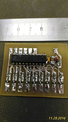
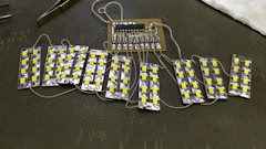
Turn signal running lights
Decided to treat my followers and to publish several articles, the benefit of not sitting all the time)
This time it will be about the control Board running the fire with the filling, used for turn signals "Ala Audi"
Implementation in hardware is not as was ordered scheme development, circuit Board and firmware, the customer himself collects because you need the maximum in a short time to make. My program is run on a breadboard, not in Proteus.
At the moment we have implemented two versions of the firmware with three versions of the Board.
And now in more detail.
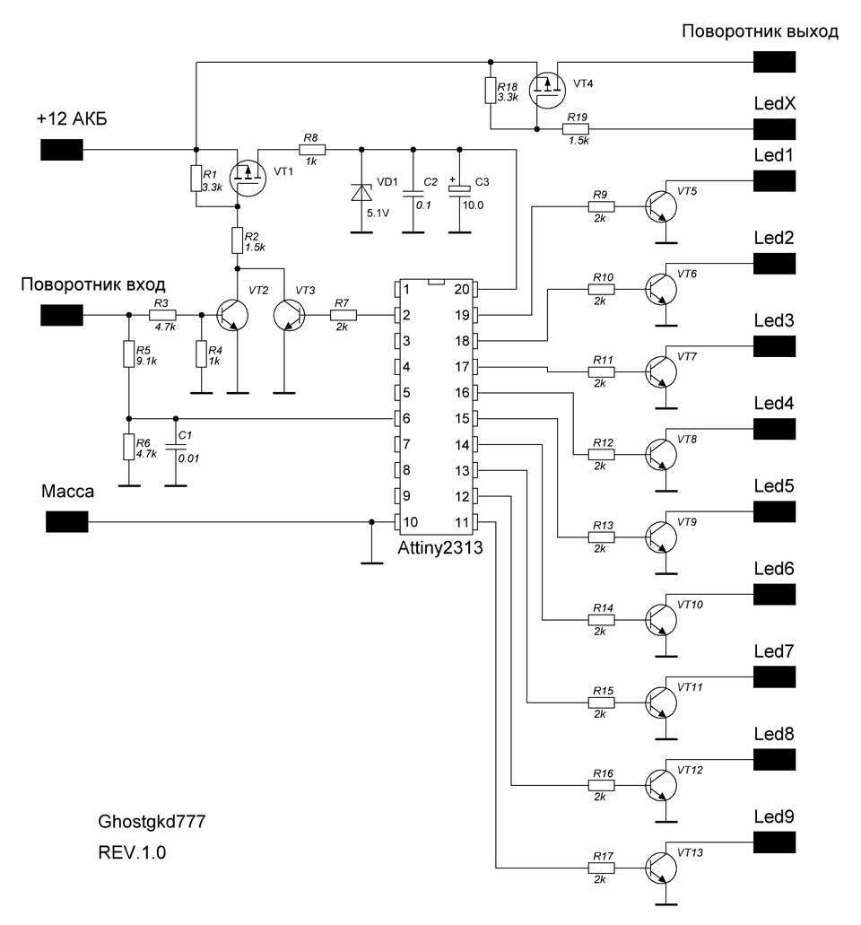
Version 1.0.
Allows you to implement the indicator "running fire" with filling on 9 channels.
Automatically disconnects from battery after turning off the turn signals, and consumes no current.
Has the function of extension cable twists ("lazy").
You can connect the lamp through the built-in field effect transistor, so get rid of the problem of asynchronous work running fire and lamp indicator. Time glow lamp indicator it is possible to change in a fairly wide range.
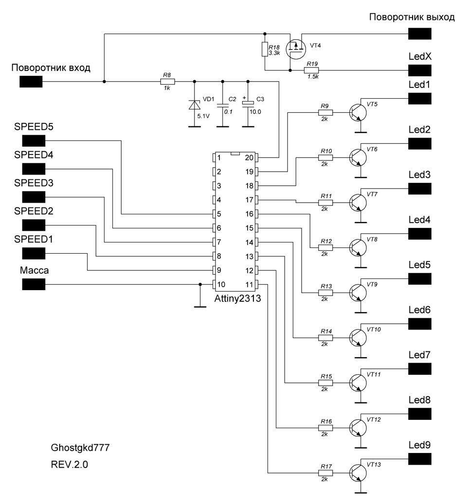
Version 2.0.
Differs from version 1 with no extension tube turns and speed regulator, ignition module LEDs to ensure the synchronism with the signal indicator.
Version 2.1.
In this version, abolished the function of lamp indicator from the controller adjusts the lighting time.
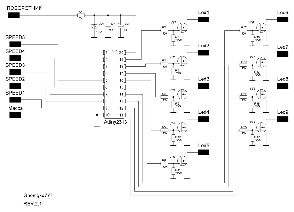
Apply the details are painted on the diagram. The transistors need to put at least the load current of led modules and a voltage of at least 20V. Recommend, as the output transistors use n-channel mosfet in the SOT-23 package.
PCB designed in DipTrace and SL for all three versions.
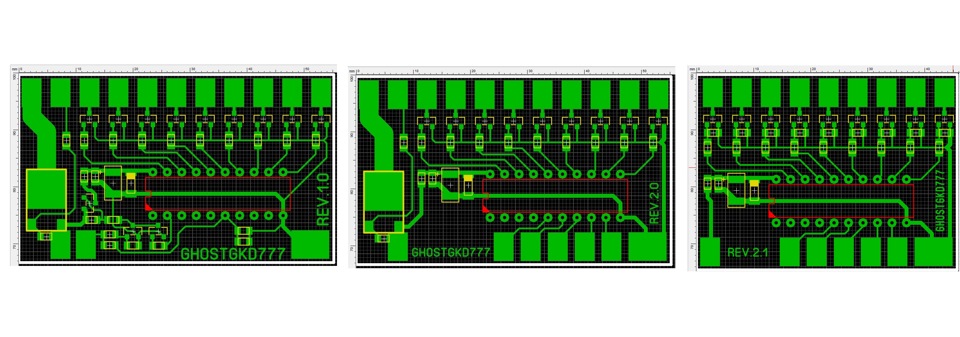
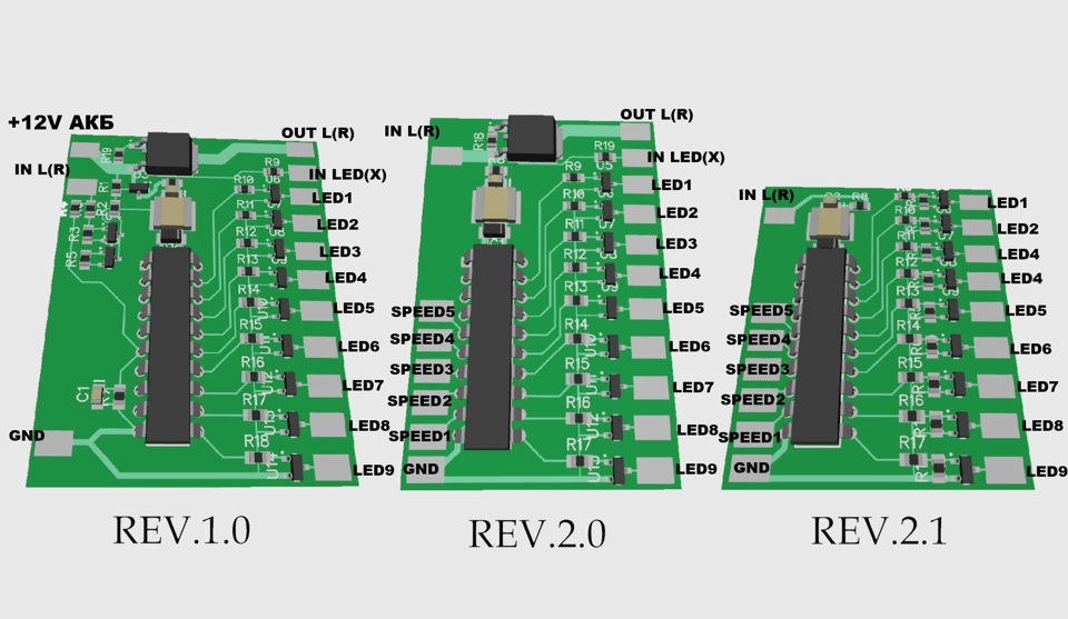
Connection
REV1.0
You need to bring to the Board power supply +12V from battery. NOT with ignition key and battery. This is the main disadvantage of this version, why, and was made second and third.
Conclusion IN L® connects to the standard wiring of the car to the wire going to the Blinker.
Led modules are connected to outputs LED1-9 and glow in the appropriate sequence.
The output OUT L® connects the indicator lamp, if the lamp remains otherwise do not connect anything.
Adjustment of the burning time of the lamp indicator is done by jumpers from the output IN LED(X) to one terminal of LED1-9. The higher the pin number, the longer the lit lamp.
REV2.0
The main advantage of this version is no need to connect your Board to battery positive, which greatly simplifies its connection. But you have to pay.
For this reason, in this version and version 2.1 is missing the function extension turns.
Adjusting the speed of the fill lights is adjusted by setting the jumpers to ground at insights SPEED1-5. The higher the number, the slower the fill. Speed adjustable fill setting in the burning time of the module in time with the turn signal lamps. Synchronization is automatic. In this version retained the ability to connect lamps to the turn signals through the MOSFET to the controller to adjust the time of burning.
REV2.1
In this version of the firmware is the same as on the 2.0, the difference is that the harvested MOSFET on the lamp indicator for the variants of implementation, when the lamp of the indicator removed and running only the module LEDs.
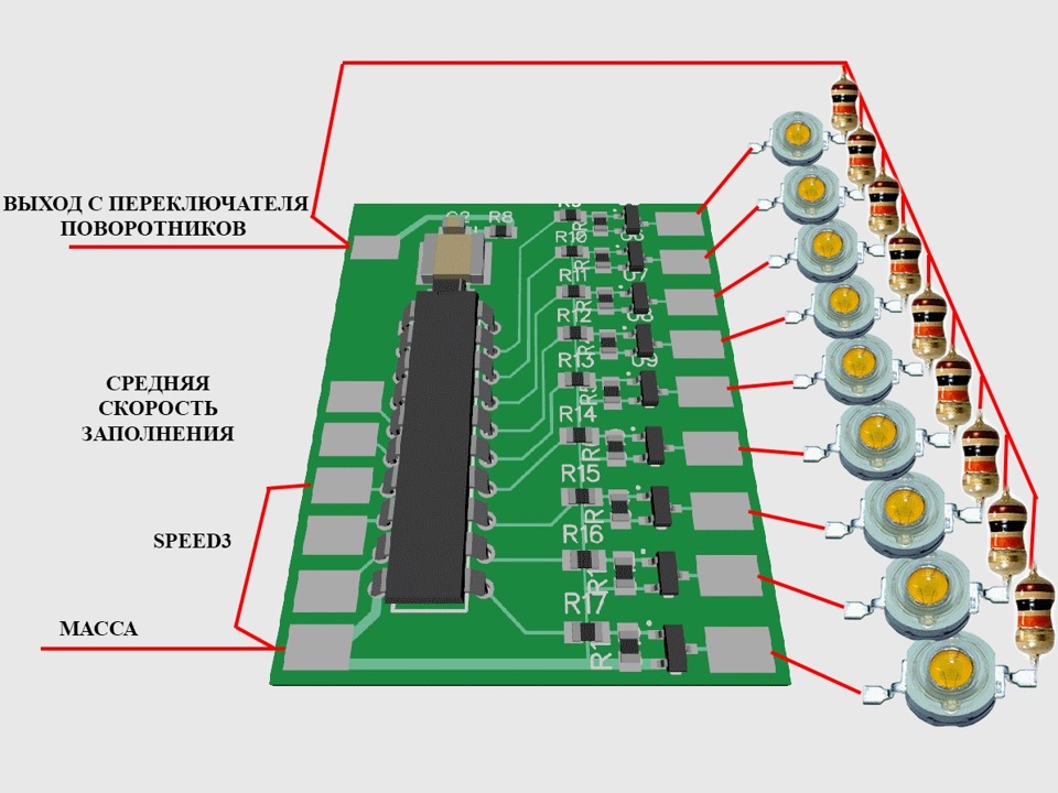
A small demonstration of the first version of the firmware:
And the second version:
Applications in the car can be a lot depending on what You are doing.
A couple of connection examples below.
 modules rear only
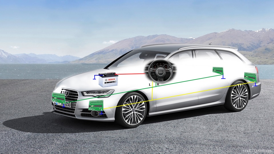 modules and front and rear
Led turn signals Running lights. Version 2.1.1.
Turn signal running lights + DRL. Version 3.
Turn signal running lights + DRL. Version 3. Testing and tuning.
Turn signal running lights + DRL. Version 3.1
Turn signal running lights + DRL. Version 3.1 Testing and tuning.
Download files to repeat Rev. 1.0
Download files to repeat Rev. 2.0
Another question. In version 2.0, which connect the output LED X speed already jumper selectable between 1-5 and earth. Something I'm confused.
Nenenet
The fuses of the controller leave at default?
In version 2.0 fieldwork irfz44n go? Transistors in sot-23 what ? BC847 go?
Yes, the fuses are default. irfz44n will fit, just need to change the fees under the case of this MOSFET. Bc847 go too. I use the mmbt2222
avareccc
everything turned out better descriptions as to collect in the whole Internet! it is good that these people are still there. thank you very much for the help!
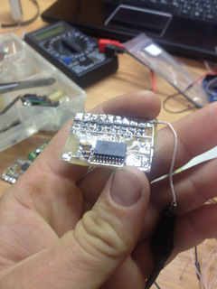
Health, very good, congratulations👍
Of course. Any npn with a voltage of at least 25V and a current of 0.5 A MOSFET or n-channel with the same parameters.
For example, mmbt2222
updated the firmware, increased the fill rate. can download it in the archive for version 2.0 or 2.1 the links at the end of the post
Hi!
All Packed up, hooked up the LEDs, only the mode a bit slow .
And will it run faster ? After connecting through relay of a fern.
updated the firmware, increased the fill rate. can download it in the archive for version 2.0 or 2.1 the links at the end of the post
Prompt in version 2.0 which gives the connection of the lamp through the fieldwork. Collected without it on a breadboard and connected to the lamp in parallel.LEDs have zagorelsya only to the 7th at the fastest speed fill. Ie can't do it zagorelsya. Collected on uln2004(2pcs.). Thanks in advance.
Very confusing to read when you do not understand. Tell me, can realize running turn signal back on Audi A5 facelift model. The same as on the A7
I apologize for the inconvenience, accidentally demolished files. All will be restored.
Very interesting to have version 1.0 Now with setup something not quite understand. In Proteus reset reset-Ohm (PD5), svetodiody lit up constantly. Next five times I connect the minus output No. 6 (PD2), as I understand the scheme has been set to zero (put out all LEDs). 1-5 times then I connect to the earth PD2 and long tap waiting for one of multiple flashing of all LEDs is the speed (частота0 traveling wave. You can continue up to 10 taps and subsequent retention on the ground that finding No. 6 is waiting for the start of work. Here, the entire line flashes at the same time. That's what this mode is. I assumed it was the hazard lights. Then the question is how the scheme to show that I turned on the hazard lights? Ghostgkd777 Jack explain that is not written or did not understand. Thank you.
Hello, can the firmware so that the diodes were lit and went out consistently because to V 3.0?
Made easier.From the designer Ali. Running lights for 20p. On 555 and СД4017(or К561ие8). To 561ИЕ8 outputs a trigger K561TM2( on a latch). 10 channel reset triggers.Further, the key to КТ815 per channel up to 1A load. And it works no worse than your controllers.Repeatability for novice radio Amateurs.
Charge paint with SprintLayOut and DipTrace
Programs are written in CodevisionAVR
Sew a homemade USBASP program Sinaprog
May have already raised this question.
Please tell me what proecu collected shemku and what pierced?
Well, people have a conscience of civil. You are given all materials for the repetition, but how to make something good enough to Google. Or do I have to remove a detailed video of how I assemble these boards?😬
Greetings. Very good article and a sensible explanation! But I have a request, could you put the video as pierces tinicu with the details. But it seems to me that I have a couple mikruhu ruined. Thanks in advance
Just as programmed . I just looked at a lot of things, but so plainly and did not understand... and the scarf for firmware gathered, but I was plagued by doubt, if I did that right)
Hello. First of all I want to thank you for the work that you did and the files that you posted. Please tell me. I collected the fee hooked up and I have poornika blink but do not run. What could be the reason?
Author handsome! I respect such people! He did and people shared! Respect to you for life!
Ghostgkd777
How connected the diodes? what? more like that the currents through them are different, because we Shine in different ways.
What version of controller?
What is the value of resistors placed in the base circuit of the transistors? 10kOhm? this is for the MOSFET. Reduce the value of resistors 2-4,7 com and You will be happy.
Version 2.1
Diodes connection through resistor 27 ohm 5 w. If you connect directly without pay all Shine evenly. Resistor in Bazovyi circuit transistors are 3.3 V kOm
How connected the diodes? what? more like that the currents through them are different, because we Shine in different ways.
What version of controller?
What is the value of resistors placed in the base circuit of the transistors? 10kOhm? this is for the MOSFET. Reduce the value of resistors 2-4,7 com and You will be happy.
I connected the diodes of 3 w and I they glow with different brightness. The transistors I put the bc 337-40 and R7-R11, R16-R19 I did not put. We need to add or transistors to change?
Health.
Yes, it's a 10kω resistor. Scheme and without it will work. It is to increase the reliability.
Good day please tell me You have a PCB version PCB_rev.2.1.3_SOIC which element is between the first leg of the chip and Board? This resistor, if so what? Also I want to tell You thank you for sharing your materials.
Good afternoon. Prompt, please, a moment. I understand that in this work — www.drive2.ru/l/9560199 the work is done by Your motherboard. I wanted to ask You as a developer, what is the current calculated output transistors. How critical transistors is connected 1W LEDs via power resistors instead of drivers ? Thank you.
Not for that. More than 1A per channel for the PCB layout loading not recommended to was my stepdad overheating the Board.
Good luck and realization!
Read to the bottom :"Any npn with a voltage of at least 25V and a current of 0.5 A MOSFET or n-channel with the same parameters.
For example, mmbt2222"
Like it became clear. Thank you.
Good.day! I wanted to ask me something is not clear for 4.7 and 47.0 UF is that condensator I understand correctly?
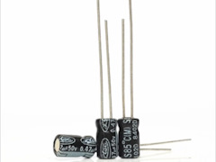
Welcome ! Please tell me how you sew the fuses, and whether they actually sew. And then I have something not working fee...
Sew through Arduino and sinaproc, and that is always there
FLASH memory has been specified, an erase cycle will be performed
To disable this feature, specify the -D option
What are you doing wrong?
nord211
Five mikruh flashed. but not works...
I have the same thing. Still can't understand. Why MK does not submit a signal to the field researcher sweethearts. How stupid is dead
Welcome. Yes, all versions require no modification of fuses. Factory: HI 64 LOW DF. Also sewed at the beginning of arduinos through Sinaproc.
Doing something wrong.
Choose the firmware file, click Program in the Flash window. After flashing and verifikatsii click Advenced... in the Fuses. The program said fuses. Check that the factory. It happens that on the new stones the fuses are different from the factory.
And what version of firmware sew?
mykruha even on the breadboard, without the transistors and rezyukah not working...
Good.
It is quite possible. Only you have to edit the firmware under a different controller and a different number of channels. None of those firmware on the Atmega8, as well as on any other, different from the Attiny2313, the controller will not work.
Success.
Good time of day. The author would like to Express my gratitude for this good deed. Himself advocating that people share with their experience.
Going to do 20 LEDs with a firmware version of v1.0 on the Atmega8 chip. Is this possible? The difficulty is that to make such firmware not able.
Yes, that's right. So the wiring diagram given in this post...
Health. Good luck.
Understood)) Improperly connected diodes. Try powered by LBP, 13 in put. Correct inclusion of the diode plus the diode on the power indicator 12 V through the resistor, negative to the Board. Right? In this mode, all works on regular 3mm diodes, all to check yet. Resistor on the power of 680 Ohms. Thank you for your work! And feedback
Welcome.
What is the voltage? Does not SAG during the operation of the turn signal? What is the value of the resistor on nutrition?
Hi! Assembled the circuit, but the output transistors are very small, the voltage changes from 0 to 1.5 V. the Collected version 2.1.4 on bipolyarnogo. Tinka prosilas is fine, the fuses are also set. What could be the reason? Photo attached
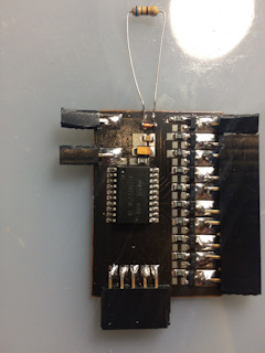
Overseer86
Long promised to write a small review but as something not reach the hands. In General, I am ashamed) so — long wanted such the turn signals, first tried to solder such a Board myself, but at least make friends with the soldering iron I have failed)) because not compatible with the programmer) acquired fees from Eugene, and I think that was right) my mouldings and boards as a picture of a first grader and a picture of the artist) but more to the point — boards excellent quality, excellent soldering, as the factory, and the factory is not in China) are working flawlessly, no need to bother on the speed setting, if you get tired of one mode you can switch to another. Overall I am happy and do not regret the money spent — the price is consistent quality. Yes, and Eugene is a nice person, talks-shows and sends the order in the shortest possible time) Thanks to him)
At what price out of the Board?
Alex, thank you for the feedback) Try to do it efficiently and as quickly as possible. Not always, unfortunately, turns out to do quite quickly — quite a lot of orders, but time is as always a little, plus there are force majeure events, but thank God not often)
In General, I try to help people)))
Long promised to write a small review but as something not reach the hands. In General, I am ashamed) so — long wanted such the turn signals, first tried to solder such a Board myself, but at least make friends with the soldering iron I have failed)) because not compatible with the programmer) acquired fees from Eugene, and I think that was right) my mouldings and boards as a picture of a first grader and a picture of the artist) but more to the point — boards excellent quality, excellent soldering, as the factory, and the factory is not in China) are working flawlessly, no need to bother on the speed setting, if you get tired of one mode you can switch to another. Overall I am happy and do not regret the money spent — the price is consistent quality. Yes, and Eugene is a nice person, talks-shows and sends the order in the shortest possible time) Thanks to him)
Please tell me how to solve the problem, I need rear turn signals didn't blink and was on fire. Is there any nakopiteli that connect between the switch turns and the turn signal and they burn constantly?
Welcome. And is there any way to alter the firmware to work on the p-channel mosfit and common advantage?
Make sure the fuses are factory. It happens even on new controllers, the fuses are not default
Hi. repeated mihalko, but fails to set the time saponine. the LEDs are lit at about 1 time per second, than it can be connected?
Hi. Thank you for your work! I'm not a radio Amateur but I really want to implement this scheme in the standard "Chinese" DRL Kia Rio 2015. Waiting for details...
Collected! Started doing the 2.0, well, in my case, and 2.1.3 was enough. Never did, I was afraid to flash the microcontroller, but it worked the first time! The capacitor is set to 4.7 µf, firmware from the folder v 2.0.rar. The only thing I have a fill rate of LEDs are arranged as pictured (1 is the slowest), and not as the author and they are faster than video. Tell me why?
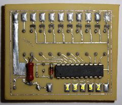
Take into account fixed — track 0.5 mm.
Himself these scarves protravel, just under the ATMega328. Firmware debug, while there is no time(((
Thank you, beautifully painted, of course, but there are a couple of comments.
The width of the power tracks is too small, such tracks are only small LEDs to turn on for 10-30mA no more, and for them, the MOSFETs are not needed.
And because of the small width of the tracks and distances between them repeatable circuit boards at home small. Not everyone will be able to repeat.
goo.gl/wyB1if — drew a charge in EasyEDA — who cares.
The amount of detail for the Board at BOM turned to penny.
EVTurkov
how to make the firmware?
A lot of programs development — Codevision AVR, Atmel Studio, WinAVR, BASCOM-AVR, IAR Embedded Workbench, Proteus... Is a development environment for microcontrollers of the AVR family.
Hello! Interesting information! But I know at got into the habit of buying you these fees! ?
Eugene Hello.For me You're just the God of electronics.All very interesting and cleverly painted.Can You help in one issue - namely, the hands I've got the rear view camera and interestingly the male plug has 6 pins(pins) SO I have not yet encountered.If you're interested I'll post a photo.
These boards control can be set to any headlight with LEDs?
I have the diodes in the head and light the foot. If you install them front and back, how to implement the running indicator in conjunction with the DRL and feet? What to do if the LEDs more?))
Hi. And it is possible that when you turn on gabaritos daytime lights burned low half?
I've read the circuit diagram and the list and how they denominations do not fight))) how true is that? In the schema, or the table?)))
Good day, would like to purchase a running Board indicator, how can they be ordered and how much it will cost?
As the traffic to this hack include?
Such as supposedly changing the mode of operation of the lighting?
So many posts, and under each so many options XS know what to do yourself and what will fit
I'm not good at electrical. but why are so many governors wires? the Parking brake on and with the oil sensor? Not enough signals with the turn signals? what thread buffer
Good evening how much will it cost the Board? Turn signal running lights + DRL. Version 3.1
Good day! how much will it cost the Board? Turn signal running lights + DRL. Version 3.1
And this modify is possible to the LEDs to more powerful supply ?
link; ru.aliexpress.com/item/2x...042311.0.0.274233edtUVlV2
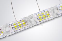
Hello! So I advise you to put the MOSFETs the ones in the description? stp12pf06? They R channel?
Hello, tell me you have translated at a constant voltage after relay without connecting to the battery? If so, tell me, how is this done?
