Smooth ignition + the brightness slider. Version 1.2
Health, fan led tuning!
Lyric entry
Life does not stand still, everything changes. And we need to develop and keep pace with the times, otherwise you will think that you're getting old and already on what does not fit :) Actually, slowly started to move on the photoresist. Really like technology compared to the LUT. Somehow about this in detail I will write as soon as the arm is stuffed. Still is one of the first crafts that I soldered using solder paste. Just apply it from the syringe on the pads, put the parts with tweezers and put a charge on a heated iron — all are sealed for 30 seconds. The idea is that you need a dispenser of paste and soldering station, but so far for my needs and enough of the syringe with the iron.
Functionality and configuration
Here I must say that this is podvetka of the project Stepan Pavlovich.
Actually, the functionality has remained the same:
— smooth ignition with speed settings and ignition delay before the start of a two channel (arrow and scale);
— brightness adjustment with memory for two modes (day and night).
I just redid the schematic and the firmware to manage the advantage in order to peresvyet all elements of the interior minimally altering the wiring of the car.
How to configure the device you can find in the parent project. Then I quote a piece of text from there.
Algorithm settings:
Off size: press and hold the button of the desired channel S1 or S2. the more flashes, the longer the delay of the channel. In one flash of a tenth of a second. 10 flashes — second, 100-flashes — 10 seconds. 200 flashes — 20 seconds, this is more than enough. Settings are saved after the releasing of the button.
When the size: press and hold the button of the desired channel S1 or S2. the more flashes, the longer the ignition. Settings are saved after the releasing of the button.
What's new in this version
1. New, smaller circuit Board for SMD components. The pads are made in increments of 3.5 mm under the appropriate terminal block, if someone is so comfortable. As keys used dual polevik IRF7316 in soic-8 housing. Each channel easily holds 30 W load.
2. The algorithm of change of brightness. Now the first 10 levels of brightness are selected 4 times slower than the rest of the range. Did so on the basis of practice. When you turn brightness, it is as if accelerated by decrease and it was difficult to catch the first few grades. Here arises the brightness of the branches of the parabola, but when I looked in the source code, I realized that Stepan Pavlovich has attended. And then I just made the adjustment of the first gray scales slower.
3. Firmware EEPROM default values.
 Scheme
Wiring diagram ignition to the wiring of the car
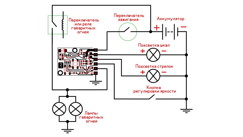 Full sizewiring Diagram for ignition
Who do not understand about the brightness on the words, I suggest to watch the video (sorry for quality, was at hand only, the Registrar):
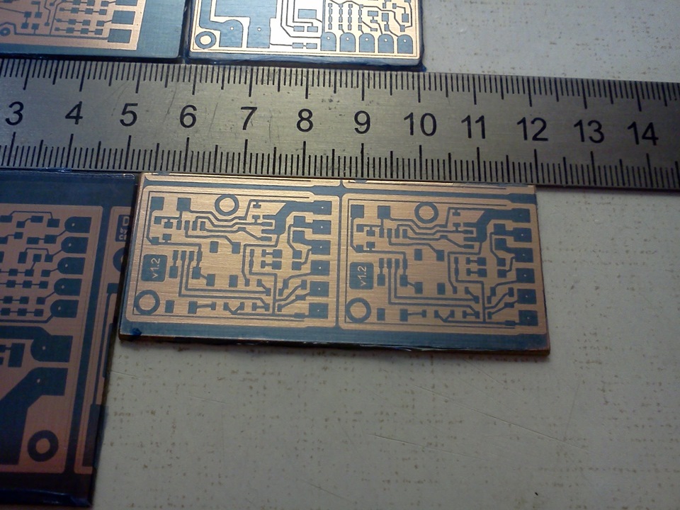 The Board is ready for baiting
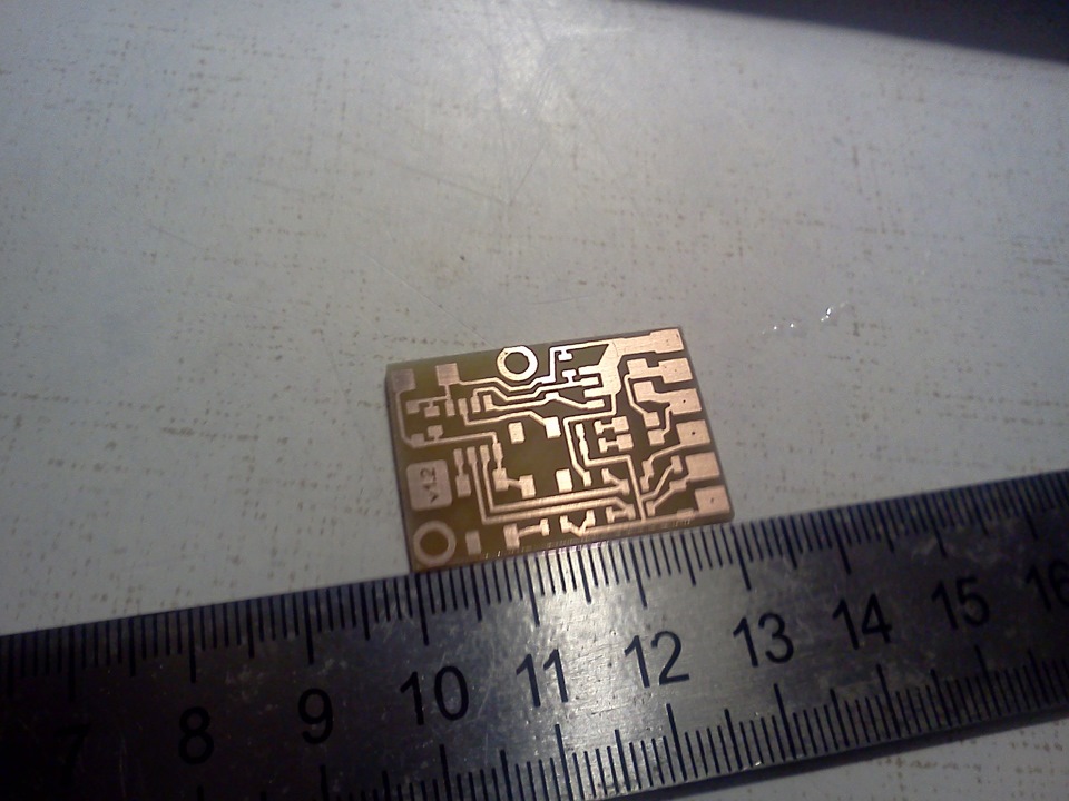 Board ready for tinning
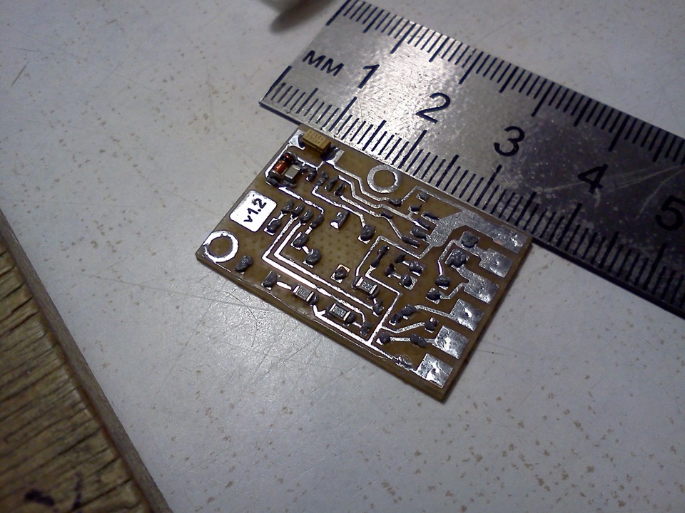 Apply solder paste and plant components
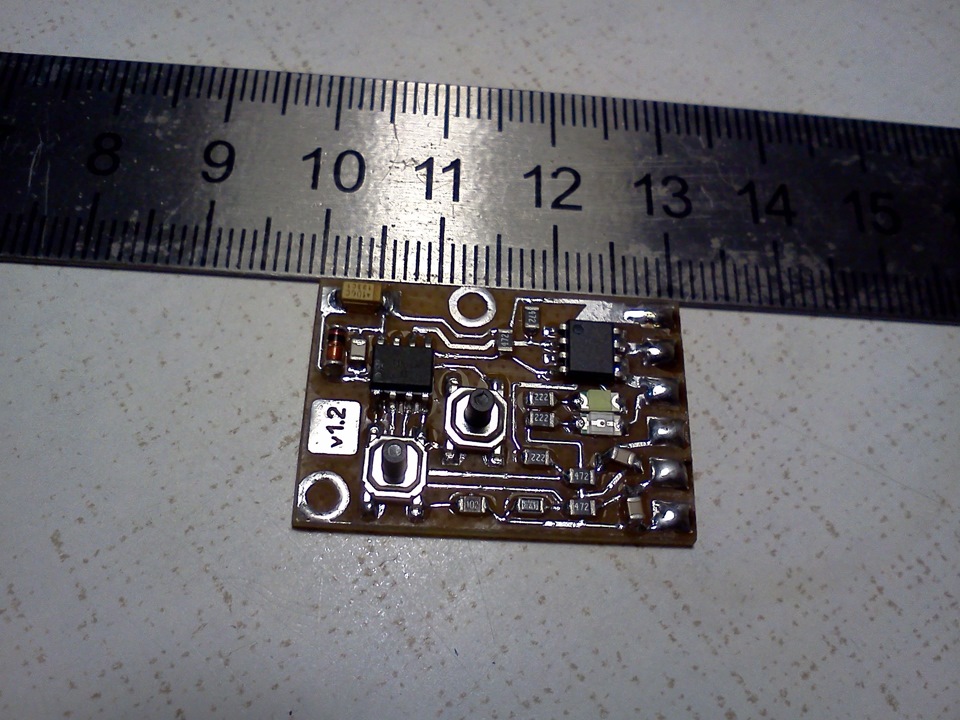 Ready device
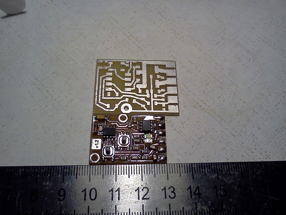 The previous version of the Board
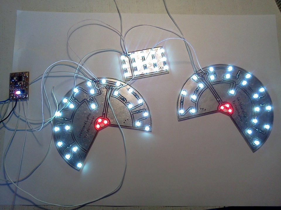 Testing
Diagram, source code, firmware, circuit Board layout you can download here
I wish you a pleasant colors in your dashboard!
I heard that some problems can be. Someone jumpers there napeval and the firmware changed. Maybe is normal, I did not use. I think the best in Electronic crafts to ask what kind to buy and from which seller.
It can be the easiest programmer for LPT port to collect, if there is a port. I gathered this. Then gathered with a colleague USBAsp and flashed the. Now USB-shnym use
How do you it in the syringe is pushed?
The need for washing, in General, depends on the model paste
And so I do GFR wash, alcohol
Got a couple to sample. Used while the one with the polyethylene yadi.sk/i/HlZf0VX2jSGQp
Usually wash off with degreaser. Anyway, after soldering you need to wash or not? Like as write that no.
Thank you. The memory of two brightness modes analog way how to do? Two whirlings? Energorayone. And here only one button. In addition, the setting of the ignition is quite wide
beautiful
the need for a controller for such a simple task, of course, under the strong question. But, on the other hand, why not
cool-hacker
www.ebay.com/itm/10PCS-NE...-SU-SMD-IC-/381375008462?
www.voltmaster-samara.ru/...m64eeprom64--atsp-ind-so8
This MK will be suitable for the repetition of your crafts? and I'm not understand anything=)
where is the microcontroller taking? One that I find in radio details for 160r sell
Ludel have a soldering iron but you can ROSE
The cost of... Parts+consumables rubles 70
Super! I still only LOOT yuzayu)))
ludel have a soldering iron or the ROSE?
what is the cost of your device?
You can try to add a capacitor. When the circuit will charge the capacitor, then bright led. But to develop and debug this scheme — there is no desire and time. Sorry.
Not really purchased, they have the power consumption greatly. This is when you switch bite. I have no worse homemade toys. Interested in variant of night . I repeat. Led at a third of capacity, with the closure of a bright glow for about a second or two. Can be more, but the glow should last a while. Simple contact will open it's not.
Reed switch, magnet and a couple of resistors then. At poklevke the magnet closes the reed switch and led is stronger. And generally not serious in my opinion it is. There are ready solutions with several levels of sensitivity, with light and sound indication. Search engines help you!
Well, how would you dealing with electronics, I suppose. Need a diagram of the collective. Shines on the floor forces the diode. At poklevke the brightness is increased to twice, three times. There are reed switches and magnets. How to do cheap and easy ?
I have a question slightly off topic. On the tip of the rod is necessary to set the led glowing, when you bite brightly luminous. Night fishing, the question is not urgent, have time to think )
co4y
See you in the thread. Tell me how to make a smooth start 2 ventilatorul cooling, that would not be drawdown at starting current?
Here is a miracle Controller start fan RPV-2 cars LADA
Controller start fan RPV-2 is used to improve the safety of operation of Electromechanical relays and the fan. RPV-2 increases the level of comfort and prolongs the life of Electromechanical relays and the fan of system of cooling of engine of Your car. Self-installation of a regulator is very simple, You'll need to embed the controller RPV-2 in the normal wiring of Your car. Controller mounting is possible in the cars of other brands, with the condition of maintaining the voltage in borotou 12 Volt outlet of Your car. When voltage is applied, the controller gradually switch on the cooling fan of the engine, smooth the supply voltage and cutting off the surge current, increases significantly the lifetime of the cooling fan of the engine.
Specifications:
Parameter Value
The supply voltage constant, At 9 to 18
Current consumption, mA, max 10
Maximum load power, W
300
Time smooth switching of the load, with at least 3
Overall dimensions with connectors (LxWxH), mm, not more 105х25х35
Weight, kg, not more than 0.01
Full service life, years, not less than 10
I think it makes little sense to run the fan smoothly. Because for a start you need a higher current than during normal operation — hence the drawdown. Although I have not tried to run the fan smoothly :) I think you can try to put a powerful capacitor which is charged through the diode to the drawdown they took over. Well, God himself commanded to run two fans not once, but one at a time :)
See you in the thread. Tell me how to make a smooth start 2 ventilatorul cooling, that would not be drawdown at starting current?
dmelnik
I am about the same. For people of all invented already.
Most of the hamsters...
The owner of the master, everyone chooses. For that functionality, the price seems adequate
It's just the factory Board is ready to be sold, one other 310 470 is, simply put and rejoice
And here is why?
Actually I also have a office plus have a smooth ignition with a bunch of settings and the brightness slider in addition. And the connection will be similar.
Perhaps for those who read the post might be interested:
There is in the sale Module of smooth illumination (WFP)
the backlight module of smooth (WFP), the module is designed for smooth and illuminate the instrument cluster of the vehicle. Module smooth highlighting WFP can work with led lamps and incandescent lamps (halogen lamps). The module is a microprocessor-based device. After applying the supply voltage. The soft-start module automatically raises the voltage from zero to the desired level. The output stage is made of MPP on the P-channel field-effect transistor that allows you to connect the module without intervention in the circuit of the instrument cluster. The module soft start working with combinations of devices, which lamps or lights powered directly from the light switch devices. ATTENTION! A short circuit in the load circuit will lead to a module failure. Its main features are:
The switch-on time of the backlight of the instrument cluster: 1.5 seconds;
Does not require disassembly of the instrument cluster;
Miniature design.
Or that the protection Module bulb low beam
The module is designed for smooth ignition halogen lamp socket H7 used in passing beam headlamps of cars LADA KALINA, LADA PRIORA and others. A smooth ignition of the spiral allows you to extend the lamp life and reduce the inrush current load on the contacts of switches and relays.
It is possible, for example, a smooth ignition of lamps with a dimmer :))) www.drive2.ru/b/2372303/
And rosin flux is useless. Take a closer look at photos — there is soldering paste for SMD components. The whole process described in the first paragraph.
cool-hacker
While the problems on any of the soldered Board was not. You probably get better as factory right? Show as need?
The photo shows that the flux is not enough. Solder coated with oxide. Rosin use or what?
While the problems on any of the soldered Board was not. You probably get better as factory right? Show as need?
So what's your argument? It turns out that any of the transistors are not suitable for smooth ignition and that's it? It's a very strange, very controversial statements.
Transistors operate for years if properly chosen for a particular scheme. — what would you pick, the result will be one) but as for the capacitors, with them, all is OK. If you put condos in the 3K Kelvin 50 diodes, and expect him long life, upset you)
Transistors operate for years if properly chosen for a particular scheme. But the first usually die aluminum electrolytic capacitors. By the way, this is the most popular cause of failure of the power supply units of computers.
Nuance not even in makeshift rations. No more reliable transistors that would be smooth ignition worked longer than three months. And if that's the case, it is easier to give up, but leave the capacitors for a smooth fade, with them age nothing will happen.
that went well!there are optitron from 35 Ki.it is possible to change it on my Mazda?
I'm not trying to humiliate, and talked more about themselves. By the way, the project is fully open, all the sources I posted in the post, and I'll be glad if someone will repeat this experience myself. Or will adopt for a more serious project.
"Life does not stand still, everything changes. And we need to develop and keep pace with the times, otherwise you will think that you're getting old and already on what does not fit :) "
so take the herd to those bought new
The connectors, which is useful if you frequently use them. If the LEDs are to power properly and slightly reduced current, they will not. Soldering was not a problem yet. In the car family on soldering circuit boards full of and it live.
And so the idea is interesting. There are a couple but ideal to do a removable LEDs to solder, if one of them goes out. And he goes out, it is even such a disease at renoshek new — tidy goes out on the mileage 12 000 km And have to do the connectors, not soldering. Cold soldering is bad.
Yes figs it knows it I think the whole is heated, either directly of course gradually.
Molochaga, too, tried to think ( turned out, but for some reason the Board is heated), or at least to find in the store.
well, I never understood) just has not caught up to what he wrote, I just its left part of the site and ordered the Bytes of the configuration. Thanks for the answer)
follow the link payalo.at.ua/c_fuse/calc.html?part=ATtiny13A
put jackdaws BODLEVEL1 and ON
get the required fuses:
6A LOW
FA HIGH
when jackdaw this means that f'yuz included and is equal to zero
Yes, I looked) a bit not Dogan that he was referring to "From the default of fuses: replaceable f'yuz BODLEVEL1 and ON" ie they don't need to sew?
himiks
Thank you for the project )
gathered up the handkerchief, the first time all worked
recently Pavlovich, too, plus did =)
Here excellent reliability, this scheme almost all of Stepan Pavlovich, you can ask him how many refused, he had them doing :)
With such noise it is better to fight not Zener diodes, but LowESR capacitors and inductances.
Though, probably, in such a simple device it is not necessary, and reliability is not critical.
From something else or was in a bad Zener diode. You're so vain the Zener diodes do not trust :)) In every stabilizer L7805, LM317, LM2596 input voltage must be 35-40 V. And in the wiring of the car, as you rightly pointed out, there are high voltage pulses with both sides, with which the Zener diode is just better cope. I have often seen in the schemes together with the stabilizer, say, 5V Zener to set the voltage higher for clipping high-voltage pulses. However, those schemes are for larger currents. In our case, the consumption of controller does not exceed 5 mA, Zener diode here enough.
Well, resistors, Yes, more of a reassurance. Although, in terms of car noise better safe than sorry.
And together we have one comrade on the Zener regulator and resistor. While the device from laboratory unit fed, all was well, but as the cars began to set, so the controller (AVR, by the way) began to demolish the roof on the first page of the firmware was erased by the garbage and the device died. The regulator LM2596 + ferrite bead fixed position.
>> You need to put a 100-200 Ohm resistor
I agree only in part. In this case, it is not required, as the PWM frequency is very low and not field workers heavy duty, capacity shutter they have a small, the switching speed of a maximum of 100 nanoseconds. Datasite Tinka on one foot, holds up to 40 mA, and in pulse mode more. She will not be anything.
>> And from the scheme are seen as powered MK. Where it the voltage regulator?
The diagram perfectly clear to the simplest parametric stabilizer Zener and the resistor.
Somewhere I've seen... Again, the leg controller drives the gate of fieldwork directly. Need to put a 100-200 Ohm resistor, otherwise there is a chance that the little transistor inside the IC will burn out.
And from the diagram it is not clear how MK is powered. Where it the voltage regulator?
For me, it's extremely difficult)) is Terribly unclear, but incredibly interesting))) As three inches, so much is placed just PPC.
There is a parametric voltage regulator Zener and the resistor keeps the power of MK at the level of 5.1 Volts.
enlighten please, you've got the circuit on the legs of MK (PB0, PB1 and PB4) of podkluchenie through a resistor to 12 volts, such a voltage will kill the microcontroller? and why not kill?
With the Chinese it happens :) I for example wonder why they often have red LEDs 3528 marked the opposite. Glad all wound up!
I do not drink))) I Understand what the problem is... ordered from China set of smd resistors. Resistors are 47kω 473 is, in itself 470Ком. It's weird, but I tested the resistor marked 473 have a real 474. MDE( now in stock no 47Комных( And rewired, and worked OO the wonders) Thank you)
Maybe we should defer, to celebrate Christmas and Pat to come back with fresh ideas? :)
cool-hacker
Pierced if EEPROM? If not, then you need to configure all the settings as I wrote above.
If you do not flash the f'yuz ON, then the firmware will be understood, as if the button on the stem of the reset pressed continuously, hence may go Margi.
nope... not working... with new tiney, indicator LEDs just light up when power is applied... zero attention on buttons and pins ILL and KEY. :(
Now a brand new MK тини13 sewed the fuses( soldered on the Board, and again the columns) is clearly wearing some of My school) EEPROM lived) 'll keep looking)
Pierced if EEPROM? If not, then you need to configure all the settings as I wrote above.
If you do not flash the f'yuz ON, then the firmware will be understood, as if the button on the stem of the reset pressed continuously, hence may go Margi.
same, I flashed with usesome specified in *.txt turned the strobe light, revived MK via hv prog and filled already with live leg of reset to use spi to firmware. Well, it turned out the strobe. leg pb0 (reset) is connected to the button so that it does not affect the work, when first turned on) button W is needed only when setting)
The pin RESET is used in the schematic and in the firmware. Sew f'yuz ON and everything will fall into place. Parametric stabilizer there is enough.
If you do not flash a flash, you will need to do the setup procedure of each option. The duration and the delay before ignition for both channels, then you need brightness switching for both modes. This will overwrite all settings in EEPROM and the next time power is applied everything should be fine
2 day torture) scarf etched, circuits soldered, no snot, no... but a flux when power is supplied somehow the indicator LEDs on the Board just arrange strobe( by pressing the buttons no response. Тиня13 alive, tried to knock through HV prog. Re-poured the firmware disabled ON. Ie left at MK reset. Also flasher-strobe. What is the trouble? May the hands of assholes?)
And well, the last time was vybesilo power design using parametric stabilizer... never liked the food. soldered 78l05 sot89 in the body. resultat the same(( mahalochki
Specifically the one with the photos he took in the Chip-NN. Now as a power supply filter in its place put ceramics in 1206 10uf
Directly in this scheme the controller of the entrance are occupied. And so you can either take one input, then there will be two levels of brightness according to the input. Or to bother with an ADC, then you can smoothly accordingly light to change.
Thank you very much. Soldering device are just beginning.
Helped to set up the circuit worked immediately.
And tell me how it is possible to fit the light sensor, assembled it on a breadboard clearly responds to the darkening of the photoresistor. But how to do that by reducing the light automatically prikazala illumination priborki don't know
I wish you health. Here are took ru.aliexpress.com/item/10...=a2g0s.9042311.0.0.kn1GGu
It does not matter in what order the main fuses were sewn at the end. After flashing the fuses will not be able to alter anything — there off leg Reset. If not flashed or flashed Ypres in Ypres something is not something you can just reconfigure the buttons each parameter and everything will be fine at the next startup.
I sewed them Sinaia prog, and flash_project never encountered, explain to the inexperienced.
Hello. The sequence of firmware is in the command file flash_project. Be careful with fuses.
Good day! I provilno realized that tinyco flash archive from the folder the EXE, then hex first EPROM?
Well, Yes, but how else to test the speed of firing and a pause in front of him? The brightness changes immediately
Tell me I understood correctly EEPROM the new settings will take effect after next power on ?
Such mylow in my ignition no. The problem I decided. Read the paragraph
"2.3. Challenges of program inversion"
here www.drive2.ru/b/1992748/
cool-hacker
Short "myrg" at the start?
I was thinking we can tie the relyuhi with a delay timer on the output .
You like scooter veteran at power up transient current is supplied to the load ?T
Health.
>> I just redid the schematic and the firmware to manage the advantage in order to peresvyet all elements of the interior minimally altering the wiring of the car.
Hello.I don't understand that you have changed the firmware on the pros or with the help of Stepan Pavlovich.Thank you.
And can you give me another firmware from Stepan Pavlovich correct.One of the first control circuit DRL.The sources I have.Thank you.
Yeah I'm not that good.I can only flash the MCU is ready hex file.On the website the Radiokote was published diagram of the Automatic DRL controller .The inclusion of DRL's happening there with increasing voltage with the smooth lighting up and fading out.All I would really want this firmware to remove the shim on the ignition and fade.
 is the future as we describe here