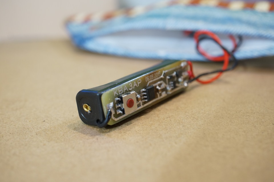
\\u0026quot;e-candle\\u0026quot; to the step-up Converter
Sometimes the space for placing the scheme on a microcontroller, powered by the battery is critically low.
You can use the battery-"tablet" CR2032, it gives 3 Volts, which is enough to operate the microcontroller. But it has a significant drawback: quite a large internal resistance. Increasing the current to ten milliamps, the voltage at the terminals of this battery can easily sink up to 1 Volt and below.
Another option is to use "mizinchikov" battery, or a battery of size AAA. This battery can easily give the amp more, but the voltage (1.5 Volt, or 1.2 Volt in the case of the battery) is not enough for the microcontroller, which requires at least 1.8 Volts at the input.
Solve one and another problem is possible using boost Converter.
Available for such a role is suitable NCP1400A (Datasheet here). It is capable of delivering current up to 100 mA and to work it requires a minimum of component:
— Schottky diode
— inductor 22uh
— input and output capacitors.
It is available in smd sot23-5
Starts when the input voltage is 0.8 Volts, and continues to operate until the voltage falls to 0.2 Volts.
Is available in various versions for different output voltage. For version 3.3 volts, the own current is less than 60мкА, and the current in the disabled state, less than 1.5 µa.
As example quote the schema on the ATtiny13A microcontroller to control the LEDs in several different modes.
Use with "tablet"
 Electronic candle battery CR2032. C2* — see below "Condenser oddities"
To conserve battery power during inactive mode the inverter is in a disabled state. To this end, the microcontroller controls its input CE, including the Converter only in active mode when it control the led and may require a significant current squander the voltage on the battery below the level needed for the microcontroller to work.
Since the battery gives 3 Volts when the Converter is inactive, the power is supplied through inductor L1 and Schottky diode D1, which lost about 0.25 Volts, and the voltage remains acceptable for operation of the microcontroller. In this case, in sleep mode the circuit consumes less than 2.5 mA and typical charge Bater enough for more than 10 years in this mode.
The use of one "mizinchikov" battery
 Electronic candle on one battery AAA. C2* — see below "Condenser oddities"
Mizinchikov voltage batteries are insufficient to power the microcontroller, so in this embodiment, the voltage Converter is always enabled. In idle mode it consumes not more than 60мкА, and although this is significantly higher than in the case described above, but the battery capacity of AAA is also significantly higher, and for operation in this mode it will last for almost 2 years.
For circuits in which the voltage Converter is switched on, there are other ICS-drivers, such as the MAX1724, the current downtime which is at 1.5 µa, but the price is several times higher.
 The scheme is assembled on the holder for one AAA battery
Capacitor weirdness
In the assembled circuits I used tantalum condenser 68мкФ, and to reduce the ESR in parallel, he hooked ceramic 2.2 UF, but for some strange reason, the controller is in idle mode for some reason consumed about 500mka. After removal of the tantalum capacitor and install ceramic 10uf, current consumption dropped to 50µa. Therefore, if the scheme is not critical to the ripple voltage, I recommend instead of electrolytic C2 68мкФ, use one or more parallel ceramic capacitors of smaller value.
Explanations to the scheme
C1, L1, D1, C2 — standard rail for NCP1400A
C3 0.47 µf — is closer to MK.
C4 1nF — suppresses a chattering of a button.
R1 — since the Converter outputs 3.3 Volts, and the output stage of the microcontroller itself has some resistance, for working white led, which is a typical voltage drop of about 3.1-3.2 Volts because of the voltage drop at the output of the microcontroller, the current will be limited at about 10mA, so if you do not want the further current limitation, R1 can not be used.
Firmware
As usual, I attach the firmware for the microcontroller with source code.
The circuit operates as follows:
— Short press on the button will turn on the circuit.
— Subsequent short pressing switch modes
— Long press (1 sec) turns off the circuit
— The scheme itself off after half an hour.
Just sold 4 modes:
1) "torch" — led shines a constant steady light
2) "candle" — the led flickers, imitating the light of a candle.
3) "pow-pow" — the led does two flashes
4) "lighthouse" — led is lit gradually and smoothly fades out.

Firmware and source code for Atmel Studio 6.2 here: zip, 40kb