The second option is a lab power supply from ATX PSU
We will focus on the technology of alteration of computer power supply unit (PSU) in the PSU.
Three years ago I published an article,"Laboratory power supply from BP at", to which the readers have shown great interest! It is worth to say that BP has already repeated this more than 20 people! Yes not all turned out all right, but I answered the comments on the article, helping to understand the problem. In the end, the joy of running BP has got it all!
Want to say a huge thank you to my readers that asked questions! First, my answers to comments have turned into a storehouse of knowledge for everyone! That's why I asked you to write questions in the article, not personal correspondence. Secondly, you helped me to improve this design! Once again thank you all who asked questions and made suggestions for improvement.
Special thanks to Yury V. Evergreen747, which along with me help you answer your many questions!
The power supply was done many years ago (much earlier than the first article!). Besides, I have altered only one instance of BP AT, and it was not possible to collect statistics on problems that can be encountered in other embodiments of these blocks. You helped me a lot to do it.
The shortcomings of the first design lab of PD are primarily associated with the lack of a standby power source. This is reflected in the fact that the PSU is not holding voltage low output at low load currents. Typically at idle to set the voltage below 5...8 fails. The second is an unstable work in constant current mode, especially at the moment of transition of the voltage: there is output voltage ripple, sometimes accompanied by a Bang or a squeak...
The power supply is suitable for power consumers and the battery charging, but for working with small electronics that require low voltage power – he's a bit rough. So I made a new power supply, making improvements, and the old one transferred to the "permanent work" in the garage.
A new version of BP
All further narration will be based on the fact that you have well studied the first article about the alteration of BP AT – I will not repeat myself, but will tell only about the modifications of the former construction from the practical side-for example create a new BP. So who has not read – go to the link and learn. The first article that you must remain "the Bible"!
So, dig through the trash at work, I was interested in one ATX PSU 400W: he's not the most modern, but for a TL494 (what we need!), protection circuit – on the LM339 (not bad), it's a nice filter power, large transformer, large capacity filter capacitors (470 UF 200V) and a solid radiators – that promised a really good power output. I dissected!
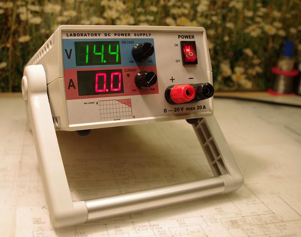 New power supply
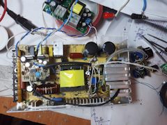
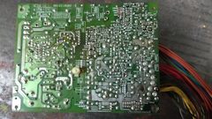
He began, naturally, with the vacuum cleaner... Then carefully examined the inside: it is made very soundly – all input circuits, the mains voltage rectifier, filter capacitors, power transistors of the Converter (MJE13009) are already "max" means umasvati it is not necessary.
After turned it on, loaded circuit +5V and +12V, bulb 12 V 35 W (very convenient to use miniature halogen bulbs for chandeliers – they easily stuck right into the connectors Mini-Fit) – works! A minute of work with this load with disconnected fan, nothing heated up, great.
Then started to look for his concept. Watched the highlights of the low-voltage parts: but it are the two most common for ATX PSU chip (TL494 and LM339), but the circuit LM339 much different (actually a lot of options). Protection power through the diode from the average allotment of the triggering transformer led to it, and we need to keep her! Nothing terrible – began to copy this piece of the schematic with the PCB. There is worse to delve into someone else's installation...
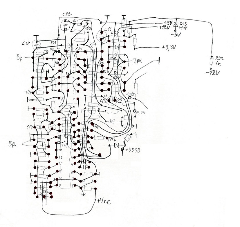 Copied the installation from the Board
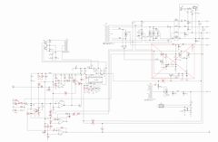
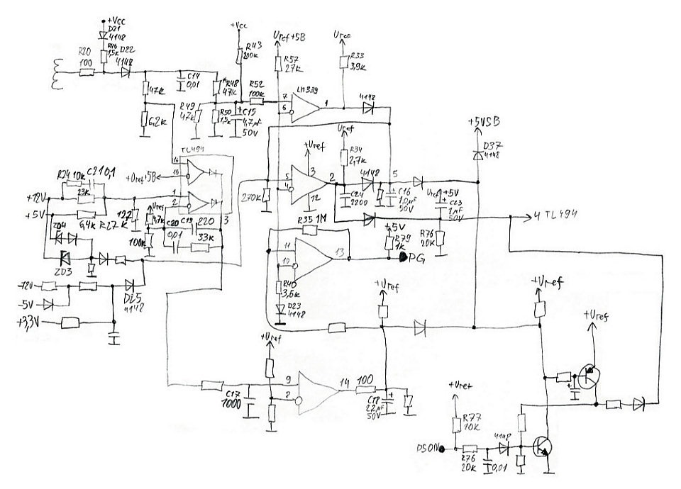 Drawn a circuit diagram. Unfortunately, not all position numbers of the elements was able to see on the Board. But the role it plays
Yeah, on excess power for LM339 comparator, the second comparator is a trigger (latch) and it also brought up the surge protection. The output of the protection routine at conclusions. 4 TL494 (which we need!). On the remaining two Comparators made the Power_Good indication. Connection diagram PSU (PS_ON) is executed on two transistors and is also brought on printin. 4. A good scheme! It is now clear what to keep and what to save:
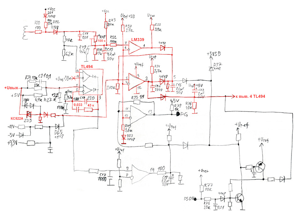 Full sizeRed boxes that you want to keep. The rest I wypal
In this case I was lucky: the protection circuit of power works through conclusions. 4 TL494. But if you look closely at the diagram of the input circuits of protection, you will see that the signal from the secondary output of the transformer runs through R20 and D22 is supplied to two voltage divider, and the first of them (the resistors 47 and 6.2 ohms) and opened also on the conclusions. 16 TL494, which we need to release. In this case, it's rude "emergency protection", duplicating the circuit for the comparator LM339 and it can be easy to clean, vypav this divisor.
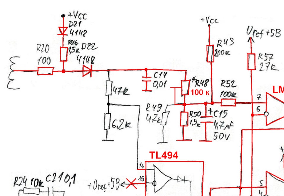 Input circuit protection circuits in power
The second divider (R48–R50), before the input of the comparator (vyv. 7 LM339) you need to turn into adjustable, you can adjust the threshold. To do this, you can substitute a fixed resistor in any of his shoulders in turn with the nominal value of 2 times more. I replaced the resistor of the upper shoulder (47 kω) for trimming of 100 ohms.
In the diagram, the surge protection is enough to replace the Zener diode ZD3 connected to circuit +12V on КС522А. By the way, to verify that this protection is sufficient to short-circuit a Zener diode with tweezers – BP should be shut down.
If your PSU protection circuit is performed using the second comparator TL494 (vyv. 15 and 16), which we need to release for the loop control voltage – I recommend to collect the most common and proven protection circuit on two transistors. Here is the complete circuit of the PD in good resolution, in which the protection circuit. But that should remain from the defense:
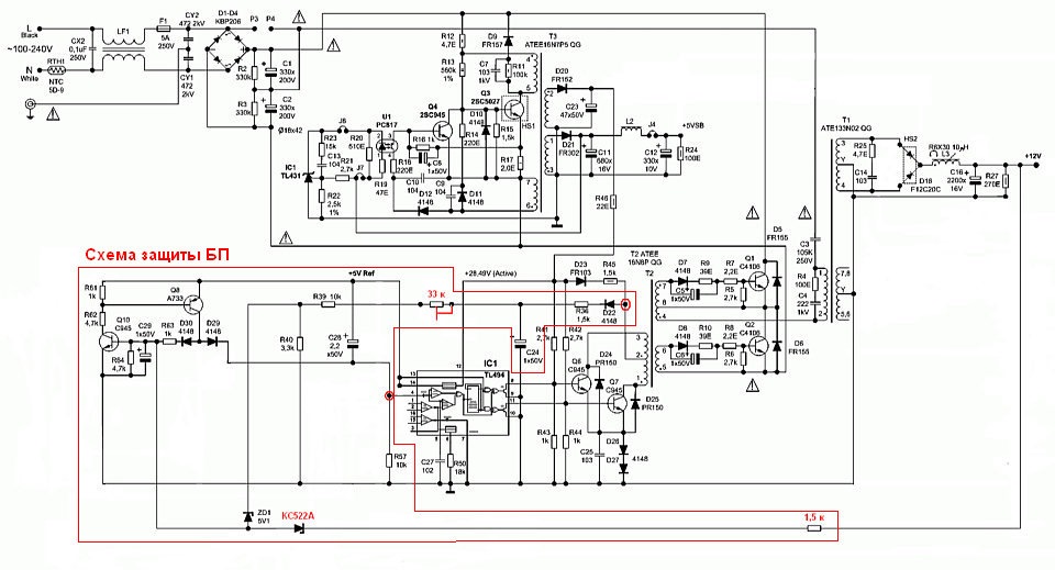 A simple circuit overload protection on two transistors. Trimming resistor 33 kOhm exhibited a threshold.
The signal is taken from the secondary of the output transformer T2, through the diode D22 and then the chain goes to the base of Q10. And with the collector of Q8 through the diode D29 is supplied to battery + 4 TL494. Also at the base of Q10 instituted surge protection output rectifier: КС522А Zener diode and a resistor of 1-1. 5 kω connected in series.
As for the rectifier and filter the output voltage, here I was also waiting for luck: rectifier +12V had the wiring on the Board to accommodate two rectifier diode assemblies in parallel (mirrored on each side of the radiator) in TO-220 case. In the filter circuit was already the second throttle (on ferrite rod) and there was enough space for the installation of electrolytic capacitors instead of regular. Then do the filter on its place, in accordance with the recommendations in the first article.
Diode Assembly for rectifier picked up com/_files/datasheets/SBR20100.pdf rel=nofollow noopener target=_blank class=c-link>SBR20100CT (20 A, 100 V, TO-220 case) of the existing house from the other computer PSU. Set two buildings in parallel, as this allowed the circuit Board.
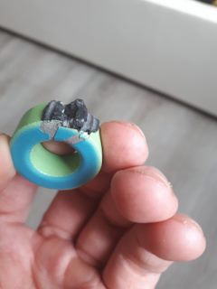
Choke group filtering I wypal, and worked with the native ring winding (coil +12V contain 12 turns). After I wound a new coil enameled wire Ø1,0 mm on the same ring 25 turns in the two wires stacked together — all as recommended in the first article. It is just 2 layers winding: on the outside of the ring coils of the second layer are located between the turns of the first layer. Shake recommend "from the middle" to each end of the winding for short the ends of the wires which need to pass through the ring. The wire you need to pull, whatever it is snug to the ring.
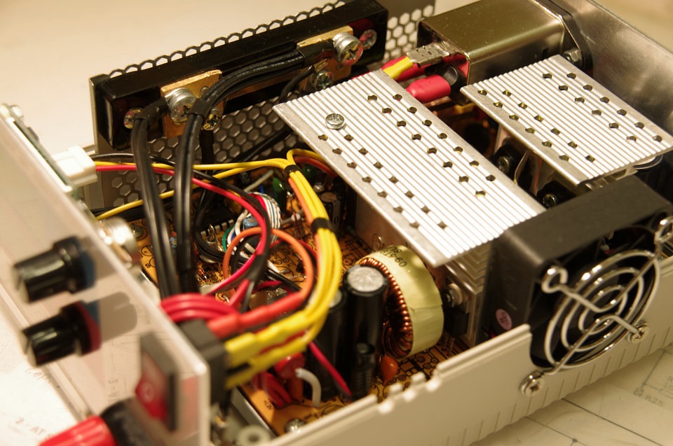 Visible elements of the rectifier. The throttle looks like a factory – I wrapped self-adhesive tape from the regular throttle...
I have a lot of industrial boards with capacitors of 1500 µf 35 V – I put in the filter instead of the regular ones. In principle, this capacity is already sufficient. Also added ceramic capacitors in parallel, and mounted resistor 100 Ohm 2 W for stable operation of the PSU without an external load. This resistor should be raised above the Board the whole length of his insights – he can heat up when setting the limit values of voltage.
The only thing you need to remember to do in a ATX PSU is to remove the circuit valittomasti from the rectifier +12V that feeds the PWM chip TL494 (vyv. 12). This is usually a diode or a diode in series with a resistor of a few Ohms. Unlike the standard scheme, the output voltage of our BP will be adjustable, and this chain will only add to the instability of the power supply for PWM. The ripple at the output from this increase. Let the PWM is powered from a standby power source.
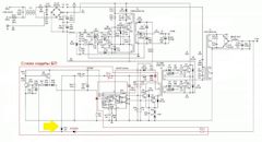
Began to see again the diagram on the website and came across a scheme similar to BP... Happens! Nothing in the title, but the only difference in the numbering of the elements on the card and the value of the capacitors large electrolytic capacitors (not surprisingly, the circuit from the PSU 300 W power) – the rest is one to one. Will show and example of the whole scheme, what was removed and what is left.
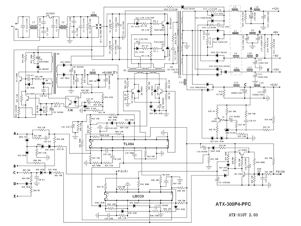 Full sizeDiagram of ATX PSU-300P4-PFC
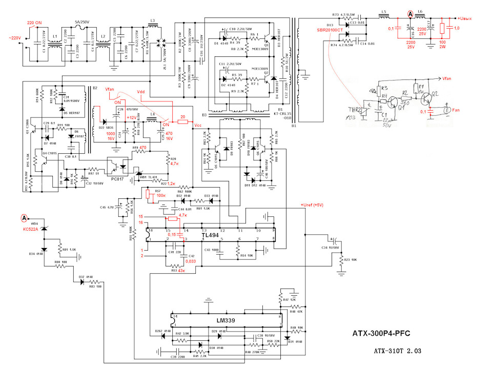 Full sizeFinal circuit after the alteration – what should ultimately remain on the Board. The red highlighted elements replaced. Some of the points listed here, I will explain below
And so, the power (high voltage) part of our order. The output rectifier and filter prepared. Protection against over power and over voltage available. Scheme off BP vipiana. Left to do the control scheme.
At this stage I recommend to test the PSU
This will reveal possible errors in the converted part will determine the maximum load capacity of the PSU, to check the temperature mode of its elements, and the operation of the circuit protection. You will be fully assured of complete efficiency of the PSU before installing the control Board.
For this you need to connect a simple voltage divider of two resistors (15 and 4.7 kOhm) and potentiometer (10...50 ohms) to the first comparator of the TL494 (vyv. 1 and 2), as shown in the diagram below. To exclude the influence of the second comparator, printin. 16 should be grounded, and conclusions. 15 apply a small voltage. In some BP this is already done – so take your time to cut these chains! My BP in the normal scheme on printin. 15 was already submitted +5 V, and conclusions. 16 remained grounded through a resistor of 6.2 ohms from the divider.
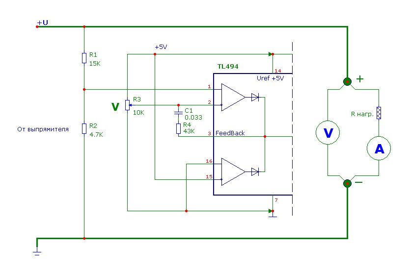 Connection diagram PSU for testing
A trial inclusion in the network of produce through the lamp filament 220V 100W included instead of the fuse. This will allow to avoid failure of power transistors. In case of excess current, the bulb just lights up, keeping the expensive transistors. Of course, the PSU receives electricity via the light bulb will not allow you to load it, so that the load test you need to make without the bulb.
Make trial inclusion. If BP does not start, check first the voltage of 300...310 In the condensers of the network rectifier, then a voltage of +12 V (or higher), which comes from the source of standby voltage on TL494 pin 12, and then the absence of voltage on vyv. 4 – if it is there, it means that the protection disables the PWM. If there are no errors then the output voltage would be continuously adjustable by potentiometer in the range from 0 to 20...21 C. If so, then you can turn off the bulb, put the fuse back and move on to testing the PSU under load.
But first take care of the cooling of the power elements! The fan can be placed at the side of the radiator that if he were well purged. Power to the fan you can recover from a standby power source (the output of the rectifier feeding the TL494), making sure there is about 12 V.
The load the PSU I use is thick (about 1 mm) nichrome wire, connecting to her "crocodiles". Resistance to change – by changing the distance between the points of connection – a classic of the slidewire. 2 m length. The wire will heat up (sometimes red hot) – so make sure it is free hanging not in contact with surrounding objects. With loads more than 10 But I use two put together a wire
BP load gradually while monitoring the voltage and current! Follow the heating power of the elements. The best option when maximum capacity radiator with power transistors, a heat sink with rectifier diodes and the choke on the ring are heated approximately equally. Don't forget that the heatsink of the power transistors is at a potential of the power network!
The vast majority of computer power supply draws a current of 10 a at A voltage of 20 V, i.e. 200 watts of power for the former 12V winding. The best option is to control the oscilloscope the duty cycle of the pulses on the secondary winding. The limit should be considered about 90% of the population (fear not, 100% will not put logic TL494). My PSU power limit on this winding was 250 watts. The threshold I set at 220...230 watts.
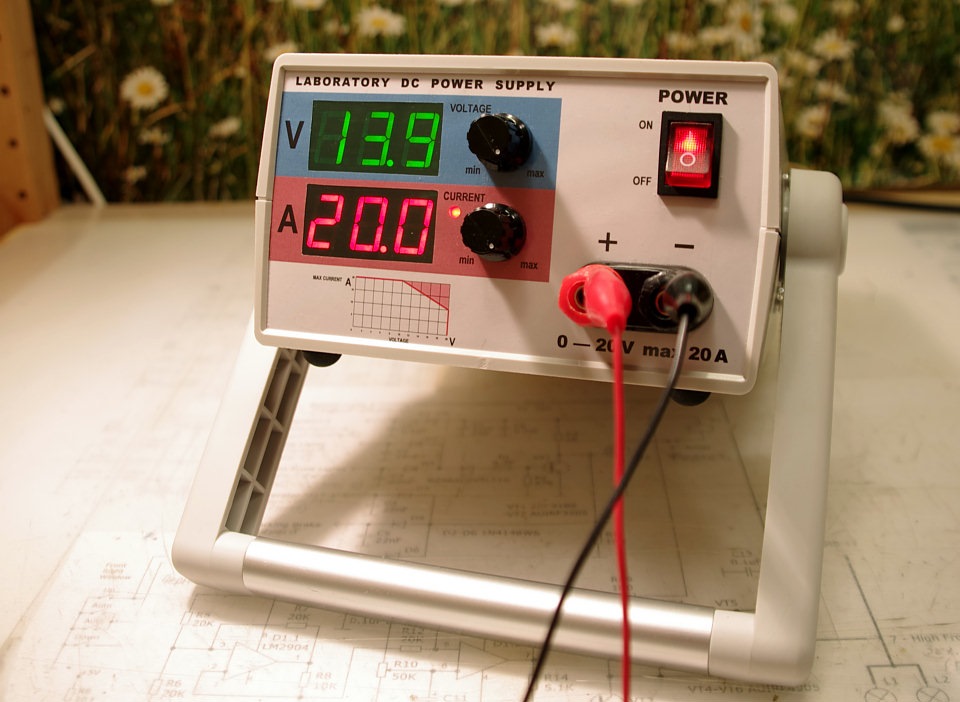 Wow value!
The heating elements were not as significant and I moved on. Tried to load the PSU with a current of 20 a at A voltage of 10 V (same 200W) – rectifier diodes and the choke started to warm up more, but tolerable. And then I decided to make limit adjustment current is 20 A. This allows the output voltage range from 0 to 10 In loading BP 20 A. current Above this voltage limit, the current will subside (this will limit us protection circuit overload) to 10 A at 20 V. for Example, when voltage of 14 V, the unit may give in the load current 16 A, which is very tempting!
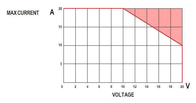 Load characteristics of the PSU. Red shaded area – the area of limiting the power output
Many complain about the POPs and squeaks under certain voltages and load currents. Testing the PSU at various loads, I also faced with this and decided to further explore this question.
Squeak is a feedback loop to adjust the output voltage from the output "+" terminal to battery + 1 TL494 (including internal comparator in it, ie as it to conclusions. 3 TL494). Self-excitation is manifested by the appearance of the ripple voltage on the output terminals of the PSU, which is perfectly visible with the oscilloscope. Primarily, this is due to chains of negative feedback (NFB) between the battery + 2 and 3, and conclusions. 15 and 3, which determine the gain in the loop adjustment. In my first design I threw out the resistors, but in vain!
You need to keep the original chain between conclusions. 2 and 3 of the TL494. I have in the old scheme (capacitor of 0.1 µf) is not the best option, you need to put a capacitor in the area...0,022 0,047 µf and a resistor of 33...68 ohms, connected in series. The resistor should be selected according to the low-excitation (squeak). Instead of a resistor I put a trimpot, 100 ohms, and forcing BP to the maximum "squeak" (selecting a combination of output voltage and load current feed), changing the resistance of this resistor was found low (easier to see with an oscilloscope the amplitude of the ripple at the output of the PSU). I, for example, the ideal chain is obtained by the combination of 0.033 microfarads and 43 com.
Later, similarly, I picked up and the values in the feedback path of the regulation of the current – RC a chain between conclusions. 15 and 3 TL494. I have a perfect chain is obtained by the combination of 0.15 µf and 4.7 kω. Capacitors these chains must differ in capacity, otherwise, the same chain appears on the self-excitation boundary of the transition from constant voltage mode to constant current mode Comparators inside TL494 start to "fight" among themselves to who will regulate the output voltage.
Also, the cause of self-excitation are voltage SAG in the conductor mass on the Board between the rectifier output voltage and a minus power supply TL494. Try to connect a short, thick jumper (wire with section not less 1.5 mm2), the average output of the secondary winding of the transformer (pigtail) sitting on the ground, with the earth near the battery + 7 IC TL494. Also the point where is soldered the earth wire from the variable resistor adjust the voltage and current should be selected near the battery + 7. The test better to do on the go: take a piece of wire 2.5 mm2 with a length of 10-12 centimeters, bend the arc and try to connect the dots.
And the third is a hum on the wires of the circuit to adjust the output voltage from the transformer – try to hang a capacitor of 0.01 UF between the battery + 2 and 7 (ground). Do in this order! Because sometimes, setting jumpers, for instance, completely removes the feedback, and then RC a chain of OOS is not to pick at a minimum.
In the end, I reduced the amplitude of the ripple at a load current of 10 A and voltage of 20 V In voltage below 5 mV, in the constant current mode is below 15 mV. This is a very high performance!
Control Board
After testing the PSU, you can go to the Assembly of the control Board. In the first option I refused to use the differential amplifier in the loop control voltage in order to reduce the number of wires. But in vain! Coefficient constant current was low, plus the voltage drop on the wires of the earth additionally introduces an error. Therefore, in the new scheme I have included both operational amplifier (op amp) in a differential mode. Type requirements remain the same OU as it is written in the first article.
Amplifier circuit adjustment voltage (DA1.1) remained unchanged. With the specified resistor values (R1=R3 and R2=R4) limit adjustment voltage corresponds to 20.0 V. For the accurate operation of the differential amplifier need to preserve the equality of these resistances in pairs. Resistors with a nominal value of 4.9 ohms is made up of two, connected in series (e.g., 3, 9, 1 kOhm or 4.7 kOhm and 200 Ohm, etc.).
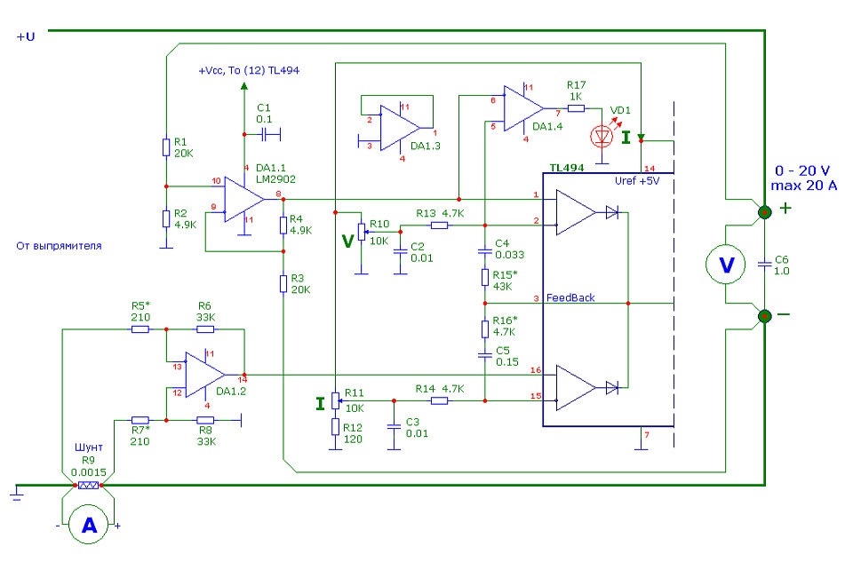 The diagram of the new control unit
Amplifier circuit adjustment current is collected by the same differential circuit OU (DA1.2), which requires the connection of its inputs a separate thin wires directly to the terminals of the shunt. The ammeter I used the old SAH0012R-50, so the shunt remained exactly the same 75ШИП1-50-05 with resistance 1.5 milliom. In this case the shunt and specified in the scheme resistor values (R5=R7 and R6=R8) limit adjustment current is 20 A. to reduce the adjustment limit current to 10 A need to reduce the resistance of the resistors R5, R7 110 Ohms. In the case of using the ammeter with a different shunt, differing in resistance to set the upper limit of the control voltage will need to change the resistance of the resistors R5 and R7 (or R6 and R8), while maintaining the equality of their resistances together.
Display mode constant current I moved to the chain tension adjustment by changing the inputs of the comparator (DA1.4) with each other. In principle, it does not matter...
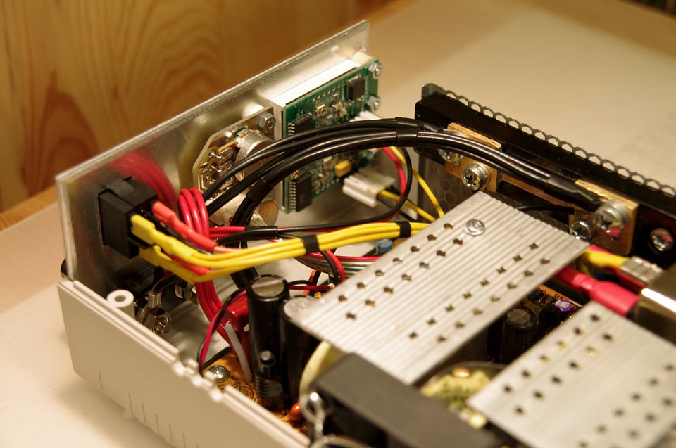 Adjustment and display located on the front panel
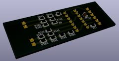
As in the previous construction, the variable resistors to control the voltage and current (R10 and R11) and R12–R14, C2 and C3 are located on a separate Board located on the front panel. The Board file format Sprint-Layout you can download from here. Chain C4, R15 (full-time) and C5, R16, located on the Board near the PSU chip TL494. The rest is on a separate Board, which can be downloaded from here. The installation is made on SMD elements.
I want to reiterate that the power and ground to the control scheme need to take from the points on the Board BP in the vicinity of conclusions. 12 and 7 TL494. The land to the variable resistors adjust the current and voltage on the front panel should also be taken near the battery + 7 TL494. The case of variable resistors must be grounded.
Stand-by power supply
Now let's talk about the internal power switching control circuit Board, voltmeter, ammeter and fan. In principle, the total current consumption of these elements is not high – it pulls perfectly stand-by power supply. But you need to take into account the pulsed nature of the load, which is primarily a fan, and measuring instruments (due to dynamic mode operation of the led digital indicators). Ripple in the power supply circuit PWM and control Board we do not need, so they need to untie together.
I went even further: stand-by power supply has two outputs: stabilized +5V_SB and a second voltage of about 12 V, which is stable parametrically (indirectly). First we don't need, and used just a second! So I moved the chain to the stabilization of the voltage output +5V_SB to the second output and set them to 12 volt (If you need for any purpose +5 V, it is possible to install integrated stabilizer LM7805 from this circuit.)
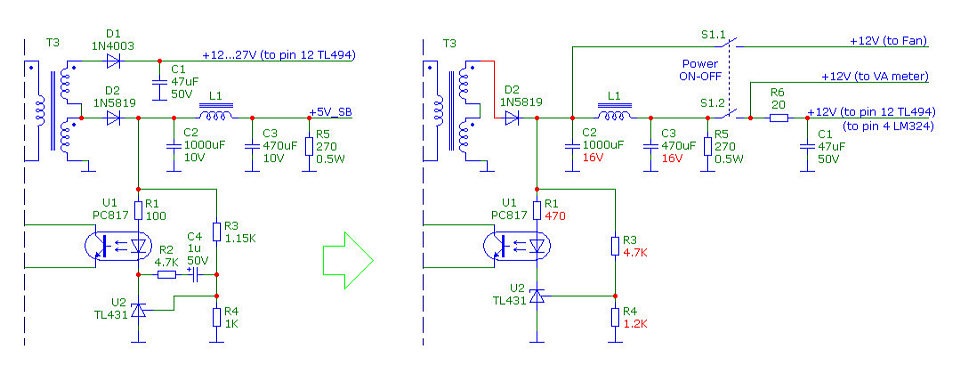 The scheme of organization of the internal from the standby power supply BP: left as it was, right as it became. Highlighted in red are the values that you want to change
As you can see, I used the wiring diagram of the power supply filter circuit +5V_SB, which comprises a throttle and a second electrolytic capacitor. The rectifier diode I used is also from this same circuit, just solder its anode to the other terminal of winding!
The first filter capacitor takes food fan. After the inductor, the second filter capacitor take the ammeter and voltmeter, and power to the TL494 control circuit flows through the resistor R6 (the resistance 15...33 Ohm) with the third capacitor (C1, state). It's a great upshot on nutrition!
The power switch
You've probably noticed that after the filing of the supply voltage, the standby source starts with a delay. Off BP too "long". It is connected with the time of charge-discharge electrolytic capacitors in the rectifier the mains voltage. So I decided that it is better to power down the block not across the network 220, and internal voltage of +12 V. It will be forced to stop the PWM (TL494). Now the power supply instantly starts and almost immediately shuts down. Please note in the diagram that the internal load resistor (R5) must remain on until the switch. Network the switch I still retained, but now it is located on the rear panel.
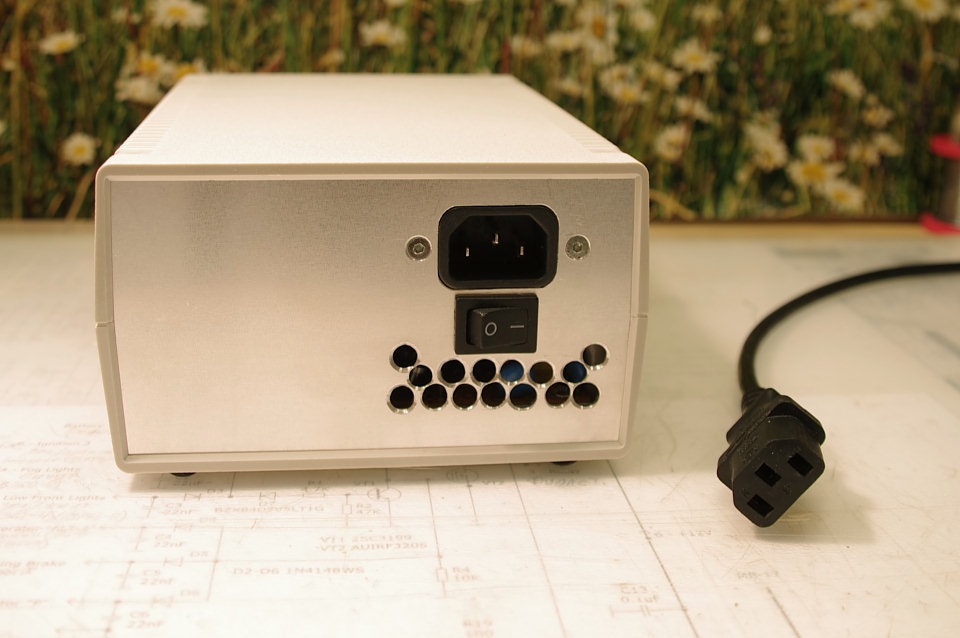 The rear panel of the power supply
Control fan speed
Well, the last thing I did not like in the old PSU is the noise from the fan. In some ATX PSU, there is a scheme of noise reduction, which controls the voltage to the fan depending on temperature. In my new PSU on the Board were distributing under this scheme, however, the fan was connected directly from 12V. Srinivas Board layout, digging in the schemes of the other PSU, I found the required component values for this circuit. In one of the modern BP wypal I needed a thermistor (10 kω), a place in which it was provided close to the radiator for cooling the rectifier diodes. Soldered it all on their own cost at regular places. The thermistor additionally glued with glue to the radiator.
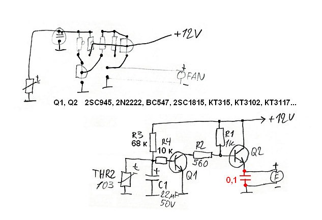 Control circuit fan speed according to temperature
I used the fan EC5015M12S (50x50 mm). Now it is initially a voltage of about 4.5 V – it is almost inaudible. And only when the heating element voltage begins to rise in proportion to the temperature. Now everything!
 The fan is in front of both radiators, but blows the entire volume of the power supply, including cool and choke the output rectifier
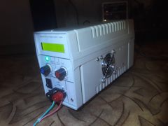
The new PSU I mounted in the same enclosure with the handleand kept the old layout of the internal parts. Front panel design has remained virtually unchanged – it is well-established from the point of view of ergonomics.
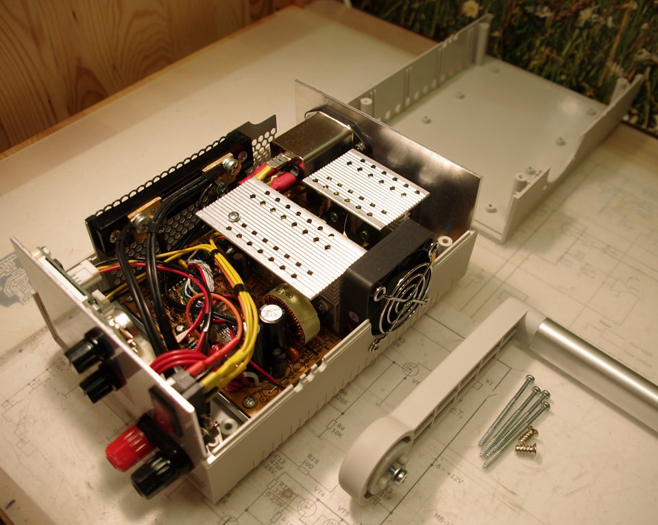 A good case for this power supply!
If interested, I can tell the technology of manufacturing the front panel in a separate article.
The power supply is so powerful and reliable that allows you to:
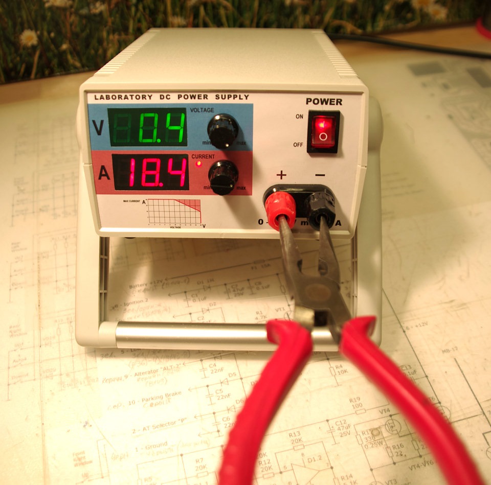
Definitely!
On TL494 with a 2-m built-in amplifiers of the error very easy to do on one the error amplifier of the adjustment speed and the second amplifier of the error you can make additional buns, for example, limiting the maximum current, or trigger the current protection. Sometimes it can be useful, for example when the blower hit something while working.
By the way, I really liked DC intelligent key IR3310, firstly it is a key top of the shoulder (ideal commuting load +line), with a low resistance in the open state, equipped with a number of customizable protection.
Thing's great, especially for cars, I tried, and could not to burn it))
And the price is very affordable.
In my opinion, a great decision, especially with time-tested efficiency. I TL494 is also more like, NE555 frequency and duty cycle are interdependent and sometimes it creates some inconvenience. And improving TL494 wider without any complexities.
Thank you!
Head something right.
Software PWM on MK, on the same AVR works.
On my car was termosoft on speed control of radiator cooling fan, asked several years ago to change it on the blower motor. Decided on the "adult" to do software PWM on AVR c PID regulation. Stuck on this topic, the testing of a simple PWM on the AVR with a linear regulation of rotation from temperature is partially launched, there are special problems are not present, but when I decided with PID regulation to do realized that this is overkill, it is homemade eats all my free time.
In the end, made analog, as a temperature sensor was used as a time LM235 not only PWM NE555, TL494 and my favorite Device is already 2 years working on cars with no complaints.
If you're interested, here is the link to the diagram
drive.google.com/file/d/0...-F7y_dHJhWThLVUM5Skk/view
here is a link to a description of the design
www.drive2.ru/b/480882131719946605/
Indeed, a good scheme. He wanted to collect for LBP intelligent system fan control using multiple sensors instead of thermistors to use a Zener LM335Z c diffusivities to a voltage proportional to temperature drift, control the duty cycle of the PWM NE555.
When on the breadboard worked, puzzled by the inclusion of the led indicator the fan. Had to fence additional comparator and set the threshold to its incorporation in accordance with the minimum voltage required to start the fan. Since voltage starting and stopping of the fan in the General case do not coincide in magnitude, had it serves its purpose to set a suitable width of the hysteresis loop with the aim to synchronize the led and fan.
Head, looking at my attempts and how it grows is clearly secondary node, proposed to simplify the use of the MC, along with the task of implementation of security features and display. To deny the chief's sincere desire from the heart to Oprogramowanie I could not, had to record his accomplices :-)).
Good day, dear colleagues!
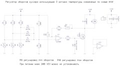
I decided to share scheme for speed control of the cooler from several sensors on the scheme OR. Maybe someone will be useful in the process of circuit surveys, for the record.
Are the owner of a 3-channel PSU, all 3 channels are independent and each channel is allocated a separate radiator. The unit is proprietary and of sufficient quality, the manufacturer, likely based on the goals of reliability, has made the scheme so that the cooler coolant is always running at maximum speed and has no adjustment depending on the temperature. When using at home at night and assuming that most of the time the PSU is not under load, to have a noisy vacuum cleaner on the table, not hunting.
Below the diagram of the regulator oborou cooler from several sensors on the scheme OR. The maximum speed of the cooler will be installed by the temperature of the hottest radiator. The number of sensors needs to increase.
Diagram of op-amp, is good because it has 2 independent parameter adjustment, blemish beginning of rotation and a second threshold at which will be the maximum speed. Also in the circuit there is a feedback which ensures a certain stability of the speed when you change the supply voltage (can be connected to the unregulated power supply). Tuned and checked for power supply and cooler on 24V, normally will work from 12V.
All the best!
Andrii451
Good evening to all forum members!
There are two screenshots of the waveform:
First. Work unit frequency 47,96 kHz. The yellow graph is the voltage waveform on the basis of one of the two power switches, red – form of voltage at the point connecting the emitter and collector of power transistors. It's all relative At -310 (rectified mains voltage).
Second. Work unit frequency 30,58 kHz. Appointment schedules too.
Load is light, about 25 watts.
Can't figure out where the climbs of the zone in the second screenshot circled in blue. The idea is that everything should be like in the first screenshot, only with a slightly different frequency. Please explain or let me read something on this topic. The next decrease in the frequency of starts unstable operation of the power supply.
Thank you!

From there climbs. What do you want when the frequency differs by 1.5 times. The transformer was designed for one frequency, and you put it in another and still want to get beautiful images in both figures.Another frequency will be a different calculation, that's when you count 30 pounds and wound it, and then show people their pictures and compare with your idea.Tricks with the change of frequency in such a range in pulse technique are not.
Marty brown's "power supply.The calculation and construction", Semenov B. Yu, "Power electronics", Meleshin VI "Transistor conversion equipment." . .
Yes please: yadi.sk/d/rJw-YeNpPG1RDw. The link to the archive in which two schemes of the multi-meter DSN VC288 and a diagram of its adaptation for inclusion in the BP Andrew.
LKNV
that is, in other words, it is possible to take a digital voltmeter, connect it to the input of the current comparator, for example when the maximum allowed on the unit current is 10A (variable resistor at the maximum) on the voltmeter is 5V, by adjusting the indicator can be achieved to show the 10V right?
here shemku drew forward voltage at 10 a is equal to 0.46 in submitting them to a separate input of op-amp through the divider 10 is achieved in the output op-amp that will serve as an indication of the maximum current, I correctly understand? but the voltage OU should be around 12-14 in not less

When used as a multi-meter common meter DSN VC288 there is quite a effective solution provides a simple means to ensure control of the magnitude of the specified current limit.
Moving the shunt from the multi-meter directly to the power circuit, first, you can easily earn multiple advantages:
— significantly reduce the error of measurement of current;
— to keep the possibility detachable connection current signal (at normal position shunt connector, this exceptional evil: it introduces an error in measurement inevitably melts);
— use to monitor current signal comfortable fine wire of reasonable length;
to improve the cooling of the shunt, placing it directly under the fan.
Second, painlessly and with a sense to withdraw the current amplifier LM358, which, in essence, is similar to the amplifier contained in remodel BP.
The levels of sensor signals and setpoint current remodel BP have the identical value of – 5V, the signal level at the ADC input that corresponds to the maximum readings of the ammeter DSN VC288 is approximately 2.5 V, i.e. twice lower. Using resistors circuit OOS removed from the meter LM358 as divider and choosing their values to obtain the division ratio of 1:2 (inexperienced can navigate under the scheme, freely available), it's easy to switch directly to the ADC input of the device or the output current of the amplifier PSU, or the setpoint current. For this purpose it is convenient to use a three-switching button: with normally closed contacts voltammeter connected to the amplifier output current and indicates the current load current, when you press and hold the button, it connects to the Adjuster and the opportunity to set the desired value of current limit without load connection.
This redesign is absolutely non-traumatic way to gauge: if you need to return it to original state (for example, for use in another device), just enough to solder into place earlier vypisannye elements.
But with this remake of the more "adult" four-digit voltampermetric (like BY-42A) is not so simple. These devices are definitely nicer to use, but schemes they do not, and the circuit current measurement is made more cleverly. Anyway, I swoop it to the end not understood, and to copy the scheme seems problematic because the Assembly is very tight and the lights fully occlude the second side of the Board. If anyone has information on this meter, I will be sincerely grateful for your help.
Sorry for the stupid question very tuno I take things for granted, not advise the right OU? I understand LM 358 will not work?
Good day! Argue you are absolutely right. And the scheme is not drawn correctly. You need a noninverting amplifier op-amp with gain=2.
Two thousand three hundred fifty
Your ammeter measures the current in the circuit, for example, it is 0.5 A. the PSU is in voltage As you say, you need to limit the current in the circuit, for example, 2 A in advance. How do you do? Short-circuit BP to a mode of stabilizatsiia and put current pokazany ammeter. And you can just set the current limit by measuring the reference voltage with the variable resistor, without loading the circuit.
Make connections on the repeater on Oh, as for your circuit multi-meter enabled right operazioni LM358, i.e. apply signal to vyv. 3, disconnecting it from the output of a previous stage.
that is, in other words, it is possible to take a digital voltmeter, connect it to the input of the current comparator, for example when the maximum allowed on the unit current is 10A (variable resistor at the maximum) on the voltmeter is 5V, by adjusting the indicator can be achieved to show the 10V right?
here shemku drew forward voltage at 10 a is equal to 0.46 in submitting them to a separate input of op-amp through the divider 10 is achieved in the output op-amp that will serve as an indication of the maximum current, I correctly understand? but the voltage OU should be around 12-14 in not less

Bola86
But if nichrome spiral only from old Hairdryers and plates?)s. They can be as load?
I'm a thick spiral took nichrome 220 tena and galogenki for blocks Petunia with the unconfigured current limit, it is certain death of the unit
Bola86
BP raised, set while transistors 13007, reading the comments — changed the diodes in the circuits of high-voltage transistors. Earned BP.
Wrapped harness of nichrome wire. Loaded with wire, gradually reduced the length between the connection points. Nothing really warming up, in addition to the load resistor.
BP food - picked up rc a chain of between 2 and 3-leg PWM, the squeak is gone. Somewhere in 20.1 and 2.2 And the tension is gone. Like PWM disabled naprugu. Although podstreshny protection on power loosened at the maximum resistance. Shut off the load, reduce the voltage regulator to a minimum connected load, again all are adjustable like normal. When you try to reduce the resistance of the load, again the tension is gone. Upon subsequent power supply voltage is regulated only up to 3.5 Volts.
Will be back to see what died. Hooked up the bulb instead of the fuse flared and went out, like KZ is not present in the high part. Looking on
It is, I had a faulty output тл494 the transistors of the buildup, and it's the key to wonder is it burnt and was not at fault and was not in the open, if there is no donkey, then at least measure the voltage on the PWM outputs
The voltage across the terminals 1 and 2 must be identical. The problem is either in the circuit of the amplifier voltage signal or a faulty TL494 itself and specified the difference between the input voltage of the upper comparator doesn't work.
The mind is not enough just to measure. at the moment in the 4th foot — 0V, 12 foot and 23.7 In, 1st - 1.2 V, 2 - to 4.39 V when the maximum unscrewed the shells
"Somewhere in 20.1 and 2.2 And the tension is gone." . . . And who's to say that there was 4 foot of the PWM at the same time, Pushkin?
BP raised, set while transistors 13007, reading the comments — changed the diodes in the circuits of high-voltage transistors. Earned BP.
Wrapped harness of nichrome wire. Loaded with wire, gradually reduced the length between the connection points. Nothing really warming up, in addition to the load resistor.
BP food - picked up rc a chain of between 2 and 3-leg PWM, the squeak is gone. Somewhere in 20.1 and 2.2 And the tension is gone. Like PWM disabled naprugu. Although podstreshny protection on power loosened at the maximum resistance. Shut off the load, reduce the voltage regulator to a minimum connected load, again all are adjustable like normal. When you try to reduce the resistance of the load, again the tension is gone. Upon subsequent power supply voltage is regulated only up to 3.5 Volts.
Will be back to see what died. Hooked up the bulb instead of the fuse flared and went out, like KZ is not present in the high part. Looking on
Д4514 fit.
Without an oscilloscope problematic to raise such PSU. Often PWM is also served and is not even always on both outputs, but only one at a time. What is happening on the PWM outputs necessary to look. Continue to dance with a tambourine will be difficult.
After BA-Bach, in the open single low ohmic resistor in the circuit 13009 and both of these parameters.
While looking for the fault I saw that all the same circuit valittomasti not removed(the diode is hidden under the cooling fin) on the diagram, D16.
The resistor was replaced, a circuit valittomasti was removed, put regular transistors to test lamp instead of a fuse flashes on and off.
Replaced the transistors H945 the situation has not improved.
Like all ring-measured everything else whole.
Put instead of regular transistors Q1,Q2 in the high-voltage side transistors D4515 (such as 700 V,15 A, whether they are suitable) — when enabled, the network lamp flashes on and off, but the PSU is not starting, TL-ke 12th leg of 23.7, on a 4 leg 0 V Is a bit to twist the resistor in the test circuit, the lamp begins to ignite, the keys Q1,Q2 are heated, the output of BP on zero. no oscilloscope to see what is happening where.
Protection from the LM key until disabled atpaw diode D31. What could you tell me where to look.
While reading the comments, kopirnul them all in ward, 2000 thousand pages)))) came out. For convenience, I can where a thread to fill in the document.
Bola86
But if nichrome spiral only from old Hairdryers and plates?)s. They can be as load?
Yeah.
you can, of heater used. In a jar with water it when it is not enough. Then he did such a thing, And keeps 30

Several times already mentioned in the comments to the article that trial runs reinvent power sources you need to use light bulbs as loads, and the need NICHROME resistance BECAUSE at the time of starting the lamp has a low "cold" resistance, which is equivalent to a short. The nominal resistance of tungsten filament lamp is obtained when it is warmed up.
The attitude of the security host and then experiment with light bulbs, if just do not, going to find replacement keys. Your case is typical.
During the test, the test of the circuit under load bahnul 13009 transistors,the load used car bulb 12volt.the last value was 8.1 volts and 7.8 amps. I think overheated the keys as there are bolts under the melted plastic washers, although the air cooling provided.while looking for replacement keys
And 7812 can be screwed. But using a powerful fan it will be pretty warm. The best solution would be to rewind the transformer of the office with a tap from 12V (instead of default 5). Alternatively, you can use additional step-down DC-DC Converter for bus 23 or increase for bus 5 (the price of a penny and no extra heat).
Resistor installed, now all is well regulated. but the question is, I have a 12 foot тл494 comes 23 Volts. the power of "pocketmate" and fan how to tie? from there take the path on the stabilizer 7812 to power the fan and "poisoner"
After removing the extra parts of the scheme would be
www.imageup.ru/img10/3394301/lc250atx.jpg.html
Just added the soft-start capacitor 1uF 50V usually stands between the legs 4 and 14 TL494.
Protection similar to this scheme
www.imageup.ru/img77/3127061/bp20.gif.html
www.drive2.ru/b/2445147/?...ge=61#a507181900100535030
If properly removed unnecessary details, the jumpers, the test scheme it should work without a problem, did not put in the output stage resistor R20 100 Om 2W?
The inductor L on the ring of DGS should have 25-30 turns.
When testing on the test schema, you can temporarily disable the protection, vypav one leg of the diode D31.
yadi.sk/i/ECrgLTp5oa5mb-all made there. however the chain where it is necessary to change the Zener to 12V — they did not exist. restored according to the scheme, however the issue with the resistor R73,the value not written in scheme.sealed was gone, I built a test version on the article.but how strange the voltage is adjustable from 0 to 20.5 In normal, and in the opposite direction is not regulated, and as if falls from the discharge of the output capacitor, what is the problem tell me. did the bulb instead of the fuse and no load
Bola86
Good day!Rework the BP in your article. I have to say that this is the third attempt to rework, the first Two with zero result. And in order not to screw up this attempt to ask for help in "poking" what desoldering correctly. PSU ATX JNC LC-250ATX. The scheme here b.radikal.ru/b24/1906/4d/61c95ee6c33b.gif. While that removed the output filters, replaced the high-voltage transistors on D13009K, the diodes in the input circuits of BP is replaced by a diode bridge GBU606, replaced high-voltage capacitors, stood 370мкф-put 720мкф.what wypal shown in the diagram here a.radikal.ru/a09/1906/79/18b121dd23b2.gif
This scheme is discussed here.
www.drive2.ru/b/2445147/?...ge=59#a502968021787084010
www.drive2.ru/b/2445147/?...ge=60#a504069182682301051
www.drive2.ru/b/2445147/?...ge=60#a505759956687913553
yadi.sk/i/ECrgLTp5oa5mb
To begin, remove all of the circuits connected to terminals 1, 2, 15, 16 shim, ground the terminal 4 and check the BP in the test scheme. You can then alter the protection scheme.
Good day!Rework the BP in your article. I have to say that this is the third attempt to rework, the first Two with zero result. And in order not to screw up this attempt to ask for help in "poking" what desoldering correctly. PSU ATX JNC LC-250ATX. The scheme here b.radikal.ru/b24/1906/4d/61c95ee6c33b.gif. While that removed the output filters, replaced the high-voltage transistors on D13009K, the diodes in the input circuits of BP is replaced by a diode bridge GBU606, replaced high-voltage capacitors, stood 370мкф-put 720мкф.what wypal shown in the diagram here a.radikal.ru/a09/1906/79/18b121dd23b2.gif
Will this PSU.
Recently domodal, finished off, finished up her first child, which began in 2016 (wanted to get rid of stuff).
Since then, the "stuff" I have added 2 oscill., generator, programmer, ... at Home sometimes look askance...
Woke up the fascination of childhood, abandoned in the aftermath.
So influenced by your articles, I remember cleaning up on the balcony about the remains of the computer and the ATX. Long I was tormented by delving into the essence, didn't like how it worked, (surge, excitement, etc...). Recently disassembled, rewound the transformer and it all got better ( continued winding 12 volts was too thin wire), also added the coils-the voltage went up to 30 volts.
Sometimes brains are skidding almost out of the blue here and need advice.
Thanks again for your work!
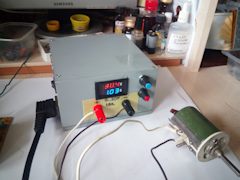
Antoshka35rf
Good time!
Began to alter, B. P ATKH - RLS ATX-250. Kind of rendered all need wypal unnecessary, but still have questions.
In schematic, I am not strong, and the knowledge is not enough.
1.Protection of power, yet did not touch, left the two transistors. as in the diagram in the article. But there is no Zener diode to the base of the transistor. Help to understand its purpose.
2.Protection I would do as you have in the article. Here is a R53 to a 12 foot ТЛ494. For what purpose he is here (from the excess power ТЛ494?). To remove it?

Good afternoon.
Don't try to change something in the protection circuit — leave it for what it is — I wrote about it in the first article. Put in place R46, R47 trimmer (face value 2 times greater than their total resistance), after that they will adjust the threshold.
I will only add a over voltage protection (Zener diode 22 In series with the resistor in the base of the first transistor Q20).
Thank you, okay.
Zener, I'm talking about another one that 5v1 VD1 which, that's it from me and there is no.
1. The purpose of the Zener is the realization of the protection function of over voltage on the output of the PSU. When the output voltage reaches a level equal to the voltage stabilizing Zener diode used (in this case 22), the Zener diode opens, starting the node protection, which, in turn, provides the signal PWM to a fourth output of the TL494 and the PSU shuts down.
All of the above was described in detail by the author in the first article, You probably just aren't enough read this carefully.
2. R53 to the power supply TL494 is not relevant. Together with R46, R47, it forms a divider which provides the initial displacement of the base of the transistor protection to install the required threshold of his release. As you increase the fill factor of the PWM capacity base will grow, and that will lead to the protection of power. In principle, it is possible to do without R53, varying the values of R45 R47...to achieve the required threshold. For example, I did just that.
Good time!
Began to alter, B. P ATKH - RLS ATX-250. Kind of rendered all need wypal unnecessary, but still have questions.
In schematic, I am not strong, and the knowledge is not enough.
1.Protection of power, yet did not touch, left the two transistors. as in the diagram in the article. But there is no Zener diode to the base of the transistor. Help to understand its purpose.
2.Protection I would do as you have in the article. Here is a R53 to a 12 foot ТЛ494. For what purpose he is here (from the excess power ТЛ494?). To remove it?

But, I understand you. I wrote above about the D39, R68.
D33, I understand, is set to not received the voltage of self-induction with the primary winding B3 of the transformer (winding in the collector circuits of the cascade excitation of high-power transistors) on the power TL494. Make it clear that off after de-energization.
Andrew, thank You very much for the answers!
On the last point a little misunderstood: the diode in Your circuit is still present (D33), and the TL494 power is exercised not through it. Still preferable to get rid of this chain?
Kotygoroshko
Andrew, thank You very much for such detailed answers! Sorry for the belated thanks, but we have a war, because of constant interruptions with the Internet.
Would like to ask a few more questions. I believe, quite simple.
1) How to choose the values of the elements of the damping circuits connected in parallel primary and secondary windings of the power transformer after rewind? I believe a meaningful calculation using formulas would be difficult because of the lack of required input data set, because there might be some empirical approaches to solve this problem?
2) a Similar problem exists with the choice of the damping circuits, shunt diodes of the output rectifier. For example, in the pattern of the original BP taken me as a donor, these chains are absent at all, although from the point of view of the competent circuit design, their presence is highly desirable. Can be of any consideration to estimate their values or to specify empirically?
3) does the above circuit in the secondary circuits of the standby power source? Reviewed dozens of schemes PSU ATX on some of the dampers is, the other isn't...
4) what is the purpose with the modification of the standard BP often eliminate the diode connected to the secondary output of the primary winding of TGR, which is powered via the cascade excitation power keys?
Good day!
1), 2) Damping of the chain reduces the q of the parasitic resonant circuits, thereby suppressing the emission "ring" at the front impulse, and protect the diodes from excessive reverse voltage. They can pick up, looking at the waveform of the signal. Their elements do not require a very careful selection.
To calculate need to know the inductance of the winding. View on forum.alaev.club/viewtopic.php?f=16&t=18
3) do Not interfere. I can say that the cases of breakdown 40 In the rectifier diode in the rectifier of the office on 12V — rare! However, where the load current is low, so you can just put a diode with a reverse voltage of 80-100 V, and it usually is.
4) This diode is good when the PSU runs with a fixed output voltage. Through him, power is supplied to the output stages and the TL494. But when we make an adjustable PSU, then at low values of the output voltage of this chain is making a strong ripple in the supply voltage TL.
Evergreen747
"And note the waveform on the size of the ejection voltage when the passive PFC." . . Do not need to pay attention to, and why in the scheme of your ATX is not powerful charging resistor. So pay attention, why not? ) ))
And I'll laugh. )
now, I don't know how much time has passed since my first publication, so far BP is almost always working fine in all modes. And you, motherfucker conceived soft dick under port 777, I guess let the unit for parts and not understanding the problem!
listen, crap — so ViDi themselves worthy! What all this a tautology?! I'm glad you learned from my article that the normal pattern of passive PFC is not only the throttle)
Lechadriver
laugh))) Though here check out how PFC vacadem.ru/blog/hardware-...er-factor-correction.html And note the waveform on the size of the ejection voltage when the passive PFC.
"And note the waveform on the size of the ejection voltage when the passive PFC." . . Do not need to pay attention to, and why in the scheme of your ATX is not powerful charging resistor. So pay attention, why not? ) ))
And I'll laugh. )
Kotygoroshko
Evergreen747 correctly described the essence, I guess You did not quite understand the meaning of the above. The principle of operation of the active CMC in this context is irrelevant, we are talking about the role of active resistance of the inductor in the aspect of limiting the charging current of the filter of the network rectifier. The emission of EMF, which is unable to resist the pathetic Chinese transistors, of course, has not been canceled, but alternatively the current-limiting resistor inductor is well suited. Just need to clearly define the problem: You are talking about dynamics, and Evergreen747 — on statics and no contradiction is actually there.
Honestly, do not care for the... Importantly, the issue is resolved. Without your extra blah-blah-blah... Well, let Your throttle current limits and that, in fact, a release of tension all the same, the transistor breaks.
...
I will not even comment, just people are not distinguished not only the statics from dynamics, but also the possible modes of operation of the keys and what they have him flying in a bucket. The easiest way to push on "China", instead ponder the depth of his question. There I was still not complete in my opinion — in coil inductance and more current to change instantly can't, and the higher L, the greater the slowdown, but it is in the case of charge network cans at the time of launch plays a small role compared to the R coil. Thank you.
Evergreen747 correctly described the essence, I guess You did not quite understand the meaning of the above. The principle of operation of the active CMC in this context is irrelevant, we are talking about the role of active resistance of the inductor in the aspect of limiting the charging current of the filter of the network rectifier. The emission of EMF, which is unable to resist the pathetic Chinese transistors, of course, has not been canceled, but alternatively the current-limiting resistor inductor is well suited. Just need to clearly define the problem: You are talking about dynamics, and Evergreen747 — on statics and no contradiction is actually there.
laugh))) Though here check out how PFC vacadem.ru/blog/hardware-...er-factor-correction.html And note the waveform on the size of the ejection voltage when the passive PFC.
"After a detailed study of what this thing is, I didn't find the thermistor, and is the last jumper". . . .
Apparently fully details just have not studied this thing. The Chinese are not for the sake of simplicity not put a power resistor in the circuit of the charge network capacitors, and due to the fact that the resistance winding of the PFC choke is sufficient and is the same resistor that did not burn the bridge and fuse.Also sometimes do it when choke coils noise suppression on the input have enough resistance.
Thanks for the advice, will take note for the future! This trouble seems to be sorted out... the First time I've seen a unit with passive PFC. After a detailed study of what this thing is, I didn't find the thermistor, but instead of the last jumper. Apparently the Chinese transistors cannot withstand the release of tension (in the inductor builds up too much energy for them) when the power supply. In General, quite got rid of the passive PFC, and all day today the unit worked flawlessly. Power supply Cooler Master RS-400.
This may be due to self-excitation of the inverter. Make sure that between the collector and base of these transistors no resistor (there is 220-270 ohms). Reduce the value of the resistor between base and emitter. There is usually 2.2 kω, supply of 1.2-1.5 ohms.
Hello everyone! Who can say why?! Burn from time to time the power transistors regardless of the load, and can at idle, and immediately after turning. Lately all happens quietly, without sound) Capacitors changed in the databases instead of the 2.2 UF 4.7 UF put. Also in the base circuit in parallel with the capacitor standing diode and the resistor on 10 Ohm, I redid the circuit, removing the resistor on 10 Ohm, but instead a second diode for reliable closing of the transistor and added a resistor of 4.7 Ohms directly in front of the base. Transistors put China aliexpress MJE13009. They know what a good workout does not hold, the crystal in them the same size as MJE13007. Nevertheless, at the very least but working in other similar remade BP, if strongly not to load. Maybe somebody was similar? What else you need to pay attention?
Scheme — www.imageup.ru/img119/298...5/microlab_350w4.gif.html
On the last point — I understand correctly that if the unit is started, and "whistles" are not "howling" — you can put the fuse, reassemble the control scheme and with a fully assembled unit more finely tune?
Thank you!
ABoosh
Good afternoon.
Thanks for the article, alter BP according to the scheme www.imageup.ru/img119/298...5/microlab_350w4.gif.html
Yesterday launched through the bulb, like a success...)
There are a few questions to understand before you move on.
1. The unit is switched on, the light illuminates briefly and goes out quickly is the charged capacitors of the input filter, and BP itself is serviceable and ready to work?
2. In the diagram, a variable resistor R21 to 47kω. Put 50kω, but in reality, when resistance 6-6,5 kω, the unit switches off as the voltage at least up to 10 V. the Lower the resistance — the voltage was raised to 20 (above the fear, I have not tried)). This is the norm, and you just have to put 10кОмный shells to fine-tune voltage protection?
3. At 15 V output and no load radiator power transistors warm but not hot, the throttle does not get hot at all, but the 100 Ohm 2 Watt output lot. Though like just a little more than a watt of energy on it at this point is weird or something is wrong?
4. Well, the last. After turning on a temporary basis to verify (without control unit) in the process of adjusting the voltage the unit is quietly whistling. Very quiet. But if you hold on to transactions for the voltage adjust potentiometer or the housing of the potentiometer — the whistle is much more audible. Hand cleaned — all apprx. the Question is — 1). A barely audible whistle is the norm or should it be completely quiet ? 2). Hand touch and the whistle is amplified pickup, and if no hands loud whistle — all the rules? I read that the body of the potentiometer should be samlit, but for a temporary test scheme did not.
Thank you!
Good day! Look here you are already helping, thank you guys for this!
1. Yes, you understand correctly. well, full health does not say, but the lack of broken transistors of the inverter podtverjdaet :))).
2. I can not understand in any scheme. Give a link to it.
3. The resistor 100 at voltage 10 V dissipates 2 watts and at a voltage of 20 V, 4 W, respectively. He must bask. Real BP with the lid closed, the inside is purged by the fan, and nothing terrible happens. I soldered it on as long as possible conclusions of the Board, to the heating of the soldering points was minimal.
4. This is normal. About this written in the article and in the comments any time. This is the tip of the wires to the shells from the running inverter, and a lead from your body. I wrote that the wires to the shells should be of minimum length and case peremennikami grounded. Do not pay attention to it. Test enable it, you need to make sure that the power portion of the PSU is working properly and the PSU is able to give full power.
The numbering of the elements of the block may differ from the schema, refer to cost.
The capacitor after D15 to ground, you can leave.
A control circuit of a fan can be added after the block settings.
Thank you, will finish.
In my block there is a capacitor just below the D15 and grounded (in similar schemes of other units so it is, so I did not unsolder), and the scheme of the "junction" of resistors R25-R73-R21 differed, but only slightly and does not matter. D55 I went to +5v, and +12 is a diode with a different designation. And there was a diagram of the fan control part of the transistor, the resistance and trim — wypal, and now slightly regret it.) But solder will not... Afraid to get lost.) Well, even the little things were "not quite right".)
ABoosh
Good afternoon.
Thanks for the article, alter BP according to the scheme www.imageup.ru/img119/298...5/microlab_350w4.gif.html
Yesterday launched through the bulb, like a success...)
There are a few questions to understand before you move on.
1. The unit is switched on, the light illuminates briefly and goes out quickly is the charged capacitors of the input filter, and BP itself is serviceable and ready to work?
2. In the diagram, a variable resistor R21 to 47kω. Put 50kω, but in reality, when resistance 6-6,5 kω, the unit switches off as the voltage at least up to 10 V. the Lower the resistance — the voltage was raised to 20 (above the fear, I have not tried)). This is the norm, and you just have to put 10кОмный shells to fine-tune voltage protection?
3. At 15 V output and no load radiator power transistors warm but not hot, the throttle does not get hot at all, but the 100 Ohm 2 Watt output lot. Though like just a little more than a watt of energy on it at this point is weird or something is wrong?
4. Well, the last. After turning on a temporary basis to verify (without control unit) in the process of adjusting the voltage the unit is quietly whistling. Very quiet. But if you hold on to transactions for the voltage adjust potentiometer or the housing of the potentiometer — the whistle is much more audible. Hand cleaned — all apprx. the Question is — 1). A barely audible whistle is the norm or should it be completely quiet ? 2). Hand touch and the whistle is amplified pickup, and if no hands loud whistle — all the rules? I read that the body of the potentiometer should be samlit, but for a temporary test scheme did not.
Thank you!
In the scheme of inaccuracy.
Leg 12 LM339 needs to stay on the ground.
www.imageup.ru/img215/340...5/microlab_350w4.gif.html
2. But if there can be let's dig... as I'm not a great expert in this.) An oscilloscope watching the output (the probe in the "plus 12" and ground to ground) — right? My oscilloscope shows a straight line, the pulses do not mind at all, interference... the Device S1-68.
3. Okay, so a 200 Ohm ceramic 5 Watt — our choice.)
4. Will povesitsya, so interesting...) It would be interesting — KORAD 3005 and the whole business...
1. The fact of the flash indicates the occurrence of the charging current of condensers of the network rectifier. The maximum current at the discharged condensers (flash), as they charge it exponentially decreases (gradual fading of a lamp).
2. 3296 multi-turn resistors are quite applicable and very comfortable, and the face value may not coincide with the model scheme. The threshold, as mentioned above Andrew, it is advisable to install at 90% fill pulse period (of course, using an oscilloscope), so everything is very individual.
3. All You're doing is right. Usually the minimum load current choose to about the middle of the adjustment range. Naturally, when the output voltage drops in proportion will decrease and the current is scary.
4. Test version, of course, still no guarantee of success. Particular installation, the topology of the Board to alter BP, the location of the shunt, the layout of remote nodes inside the body – all this has an impact on performance. Because you will inevitably have to experiment, choosing the most favorable combination of factors. It is important once or twice to touch the issue with my own hands, than to read a hundred pages of instruction. Time consuming, but what can you do...
Thanks for the reply.
1. I was more bothered by the fact of "flash" at the start, but if it's "not an accident" then OK, let's move on.
2. Somewhere here I read that reusable make interference... But I have realized that instead of healthy "krutilki" we need to buy if the blue mnogobrojni and solder it to the Board. I was more embarrassed that the schema specifies 47kω, and the fact and 10 kOhm is enough for regulation — but apparently it "features of each scheme".
3. About power resistor — tired, in my mind thought that about 1 Watt should be, and You are right it is 2.25. At 20 In — it is 4 that is likely to be after prolonged use of BP is deadly to the resistor. Buy ceramics for 5 Watts. And about the face value here is not understood. If the current required from the 50mA, and the voltage for 100 a Lot of the resistor should be at least 5 V. But even now it is adjustable from zero. What am I doing wrong?( The scheme will, thank you.
4. Thanks for the tips, I'll try. Does it only make sense to do a "test" of inclusion, because in "combat" version of it will be a bit different? Or — if in the test all will be quiet — it is an indicator that everything is in order?))
While Andrew is missing, I will Express my own opinion.
1. Unequivocally say that the PSU that are OK – not quite right. But an emergency is not clear.
2. It is more convenient to use a multiturn resistor with the least resistance to improve the accuracy of installation of the required threshold.
3. Not so. First, when the output voltage is 15 V and the resistor 100 Ohm allocated to it the power is 2.25 W, even for dvuhsvetnoe resistor too much, so it's best to use pyatiletny. Second, the resistor is clearly too low. For normal operation the PSU is sufficient minimum load current 50...60 mA, i.e., the resistance of the resistor can be safely tripled to reduce the dissipated power on it. Even better – use as a load current regulator of the four parts (a diagram can be found in the comments): current will depend on the established level of the output voltage.
4. Ideally, the whistle should not be at all, although barely audible sometimes still occurs (the reason is the design used by BP, sometimes whistles the on-call room). A bad symptom is the change of the height and volume of the whistle at various levels of output voltage and load current.
Ground the case of the resistors, and the maximum will shorten the wires leading to them. It is best to use shielded wire.
Good afternoon.
Thanks for the article, alter BP according to the scheme www.imageup.ru/img119/298...5/microlab_350w4.gif.html
Yesterday launched through the bulb, like a success...)
There are a few questions to understand before you move on.
1. The unit is switched on, the light illuminates briefly and goes out quickly is the charged capacitors of the input filter, and BP itself is serviceable and ready to work?
2. In the diagram, a variable resistor R21 to 47kω. Put 50kω, but in reality, when resistance 6-6,5 kω, the unit switches off as the voltage at least up to 10 V. the Lower the resistance — the voltage was raised to 20 (above the fear, I have not tried)). This is the norm, and you just have to put 10кОмный shells to fine-tune voltage protection?
3. At 15 V output and no load radiator power transistors warm but not hot, the throttle does not get hot at all, but the 100 Ohm 2 Watt output lot. Though like just a little more than a watt of energy on it at this point is weird or something is wrong?
4. Well, the last. After turning on a temporary basis to verify (without control unit) in the process of adjusting the voltage the unit is quietly whistling. Very quiet. But if you hold on to transactions for the voltage adjust potentiometer or the housing of the potentiometer — the whistle is much more audible. Hand cleaned — all apprx. the Question is — 1). A barely audible whistle is the norm or should it be completely quiet ? 2). Hand touch and the whistle is amplified pickup, and if no hands loud whistle — all the rules? I read that the body of the potentiometer should be samlit, but for a temporary test scheme did not.
Thank you!
now, I don't know how much time has passed since my first publication, so far BP is almost always working fine in all modes. And you, motherfucker conceived soft dick under port 777, I guess let the unit for parts and not understanding the problem!
Comment has been deleted
Feels his impunity in the distance, go on, push-button hiroi.
Thanks for the reply. Unfortunately, the attempt to find in the comments is difficult... ( Really need some kind of "wiki" to do on this topic.
Will do — I will write result. ) Thanks again.
Well.
About the led repeatedly wrote in the comments. I repeat for the 20th time: Is the problem of "curves" of the Comparators in the composition КА7500 — they're "primitive", and the differential voltage is high they may be — for BP — it doesn't matter. And your external comparator "perfect". So they are not simultaneously triggered.
You need to add a voltage divider on one of the inputs of an external comparator and adjust it to synchronous operation with the internal comparator КА7500 to the led switched synchronously with the switching to the stabilization mode current.
The parameters of the divider, for example, the upper shoulder, for example, 1 kOhm, lower 100 — 1000 ohms.
Two thousand three hundred fifty
Good afternoon. You need to dig the chain 4. of. You need to understand where there is tension. Try parascale disable protection.
Such was the case when the person soldered the Zener diode overvoltage protection reverse polarity (or it is defective). Try to disconnect temporarily.
Addition: When checking the current controller should be max (at least not to zero!), to ensure that there was no restriction of current with increasing voltage. (I even set R12 in the control circuit, to avoid this mode.)
Dug the regulator protection on power was incorrect (to put it mildly). Regulated — unit earned in defense of not falling. Current regulator put on the maximum.
Load galogenki 12V, the voltage is gradually raised each time from 0 to 12V. In the range from 0 to 1V block crackled above the silence or almost silence. 12V, 3.8 A — while so, the above did not.
The current limit works, is also checked. Paraline srode everything works. Happily) Cod in the range of to 1 volt I will try to clean up the selection of chains of feedback.
(Another caveat first limited was a current of 0.8 A, rewired R5 and R7 in the control circuit with a 1K to 10K — range is accordingly expanded.)
What upsets and itchy "what did I do wrong" — the led lights up immediately as add tension, and occasionally for a short time and goes out when the voltage regulation.
I correctly understand the work of OU DA1.4 as a comparator if the voltage at the inputs 5 and 6 are equal, the output of 7 will be 0 V And the led will light up because the output is not 0, and thus the voltage at the inputs 5 and 6 different? If so — then the voltage on the 1 and 2 legs КА7500 also must be different.
We measured the difference in these two legs of 0.005 V. During voltage measurement on the 2nd leg to block something starts to crack, led to this moment often pomahival. What could it be? Thank you.
Thanks for the tips. The Zener will check or at least be temporarily removed. Inclusion in a test he was standing, everything worked, why the option to "reverse" the inclusion of incredible, but still check (could have time to burn).
R12 installed. The current regulator set in the middle position, and in the extreme — without any effect.
Good afternoon. You need to dig the chain 4. of. You need to understand where there is tension. Try parascale disable protection.
Such was the case when the person soldered the Zener diode overvoltage protection reverse polarity (or it is defective). Try to disconnect temporarily.
Addition: When checking the current controller should be max (at least not to zero!), to ensure that there was no restriction of current with increasing voltage. (I even set R12 in the control circuit, to avoid this mode.)
Soldered control scheme, dismantled the test circuit, connect all to the unit.
Scheme — www.imageup.ru/img119/298...5/microlab_350w4.gif.html
As volmeter and ammeter hooked up the multimeter (ammeter works old 830 minutes). The resistance R5 and R7 have done 1K. What is the shunt in the multimeter is unknown.
Enable no load — triggered protection (voltage appears on the 4 leg), ignited svetodiody VD1 to the control circuit. Potentiometers twist to a minimum after the inclusion of the protection does not work on the 4-th leg 0 V Is just a little "add" voltage regulation — immediately triggered protection. Where to dig? Thank you.
I have the feeling that there is something banal, but the children do not have enough (.
Characteristics, he reverse voltage to 200 — so that you can safely!
If the capacitors 16 and above — they leave. Yes the values as I have. Don't forget the load resistor. Will bask its face value increase to 470 Ohm.
Good evening!
Please tell me, in the standby power supply on the +5VSB output, I have used diode Schottky F06C20C, is it possible to use the output 12V? What capacity capacitors need to put before the throttle and after, if I stand 2200u?
A regular capacitor C12 470u 25v remains on, resistor values, supply as you have in the scheme? Thanks for the help.

Yeah, pretty much. In the first article written about it in detail.
Let's see what the total nominal value of these three resistors connected in parallel and select the value turn in 2 times more.
Good evening.
Thanks for the help. I have a couple of questions.
I understand correctly, in my circuit the output of the block to leave only the +12V rail, and the parts with lines of +5,-5,-12V is necessary to remove and rewind the choke filtration group on +12V?
What the value should be a variable resistor?
Good day!
Want to make a computer PSU EVER MPT-301P PSU for your article. Knowledge on electronics is small,
so please help. Can remove me from drawn diagrams all unnecessary or can suggest such a scheme was discussed on the forum? The scheme is attached.

koss5
Gathered all work. Thank You Andrew.
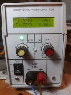
Good day, I like the link to the diagram of the multimeter will not share?
Thanks I Want to add that this option is the most successful. Had from a to z to read and consider all the flaws .
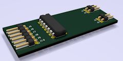
A copy of your circuit of the error amplifier. Made on a LM324N in DIP package. Drawn in KiCad. If anyone is interested tomorrow Doris and I throw off the link to the project. Board size 60X22 mm.
Olegkadd
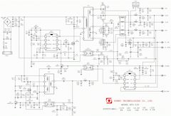
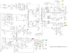
Good evening everyone. Gave PSU ENlight GPS-300ab-100v on UC3843 and DWA101N N141. After inspection replaced the swollen capacitor in the duty room, the duty room loaded automotive lamp unit hooked up through a 100W light bulb. The unit is switched on, the bulb starts flashing (audible whistling like the unit wants to start) and so on until turned off. No load office light bulb just lit. The output voltage does not appear, and the duty room about 4.6 V. the Circuit in an Internet did not find, can someone share the diagram. I can not properly run it.

vb99
The diagram on the forehead, under the name of BP in most cases find does not work. It is necessary to revise the scheme of BP on UC3843 and find the most similar (the Chinese one and the same pattern with only minor differences heap blocks rivet). Something tells me that this DWA101N N141 from the category of supervisors type WT7525, etc. Here are a couple of diagrams, see if any of these work. What about starting PD.
At idle, without load, without trying to start the main BP in the duty room what is the voltage?
Check emergency food if it is normal, start the main PSU through the bulb (in the duty room with no extra loads in the form of light bulbs meshing is not necessary).
After launch, as I understand it, a lamp lights up and stays on.
This can be either due to breakdown of power MOSFET in inverter or other power circuits. I would be looking at this posledovatelnosti: the Guardroom, the power MOSFET, the UC3843 power into these outlets, the output diode assemblies (for quick you can just check the resistance using an ohmmeter, the output lines relative to the common wire), supervisor(security). For good, something substantive to say knowing what scheme the block)
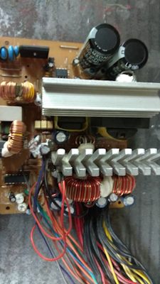
Clear. If we take as a basis for this scheme, the power for the UC3843 is supplied via a key on the transistor Q2 which, through decoupling the optocoupler IC3 is controlled by the protection circuit. The power is generated in the secondary winding of the transformer T2 dialego source. On circumstantial evidence, when enabled, starts turning cooler, suggests that BP is trying to start, then immediately goes into protect for some reason. If you are sure that the MOSFET Q1 okay, then check all of the diode assemblies Schottky on the output. They can be broken. With the Schottky diodes need to be on the alert, for all their good properties (speed, low voltage drop in the open transition) they have a weak point, very easy to break when exceeding the reverse voltage. I repeatedly faced that the Schottky diode fought a clever way that if you check the conventional tester for semiconductor continuity can transition to zvonnitsa absolutely fine, but there is a diode to put into the scheme, and submit it is already more substantial than the voltage that gives the tester on continuity can, the diode goes into short circuit.
The MOSFET checked as in the circuit Board or drinking?
Thank you. Really made a mistake measuring the power, DIP-8 UC3843 voltage of the MOSFET in the inverter is one.The scheme is similar to that only a supervisor DWA101N N141 DIP 14

Something. In normal operation, UC3843, in principle, may not be such a voltage.Even if there is no schemes for external voltage limits, then it is within the Zener to 36V. In which case is UC3843 (DIP 8 or 14 ?) On a leg to measure the voltage and relative to what? Accidentally relative to the common wire cold part of BP? ))) Clearly measure the voltage between the legs of the chip on the Datasheet.
Here is the Datasheet zipstore.ru/wa-data/public/blog/download/3843b.pdf
MOSFET in the inverter is one or a pair?
The duty room on what has been done?
It is better to find a pattern to guess
Look at what made the main PWM and PWM the duty room, which the supervisor and inflate schemes suitable and then look at ways, in the Board mount which is most suitable.
Here are the links
www.rom.by/forum/Shemy_BP
comp0.ru/schema.html
electro-tech.narod.ru/schematics/power/comp.htm
zremcom.ru/scheme-atx
diodnik.com/cxemy-kompyut...rnyx-blokov-pitaniya-atx/
danyk.cz/s_atx_en.html
www.sector.biz.ua/docs/po...chemes.phtml#.XTmSYfIzZdi
elwo.ru/load/knigi/bp_atx_skhema/2-1-0-292
maybe then someone will respond who that such a unit has faced and will tell you which scheme is more suitable
Checked.After the start lamp lights and stays on. The guardroom 5V, power MOSFET a, UC3843 power 153В, when you start twitching a little cooling fan.Output voltage no.To the circuit closer is probably the last thing you posted.DWA101N 14 feet.
The diagram on the forehead, under the name of BP in most cases find does not work. It is necessary to revise the scheme of BP on UC3843 and find the most similar (the Chinese one and the same pattern with only minor differences heap blocks rivet). Something tells me that this DWA101N N141 from the category of supervisors type WT7525, etc. Here are a couple of diagrams, see if any of these work. What about starting PD.
At idle, without load, without trying to start the main BP in the duty room what is the voltage?
Check emergency food if it is normal, start the main PSU through the bulb (in the duty room with no extra loads in the form of light bulbs meshing is not necessary).
After launch, as I understand it, a lamp lights up and stays on.
This can be either due to breakdown of power MOSFET in inverter or other power circuits. I would be looking at this posledovatelnosti: the Guardroom, the power MOSFET, the UC3843 power into these outlets, the output diode assemblies (for quick you can just check the resistance using an ohmmeter, the output lines relative to the common wire), supervisor(security). For good, something substantive to say knowing what scheme the block)
Good evening everyone. Gave PSU ENlight GPS-300ab-100v on UC3843 and DWA101N N141. After inspection replaced the swollen capacitor in the duty room, the duty room loaded automotive lamp unit hooked up through a 100W light bulb. The unit is switched on, the bulb starts flashing (audible whistling like the unit wants to start) and so on until turned off. No load office light bulb just lit. The output voltage does not appear, and the duty room about 4.6 V. the Circuit in an Internet did not find, can someone share the diagram. I can not properly run it.

vb99
I would also draw your attention to the fact that Kotygoroshko mentions, namely, the power voltage compensating stage (buildup). In most circuits ATX power supply on TL494 with source duty 12V voltage supply PWM this voltage only at the initial moment of start of PD. Further, the power is connected with the secondary circuits of the PSU, the voltage enters the PWM and matching cascade already much higher in most cases more than 20 volts. Matching transistors of the cascade are obtained through current-limiting resistor (typically about 1.5 kω) which sets the collector current of these transistors and primary winding of the matching transformer of the order of 20mA. If you cascade power this from 12V, it is desirable to reduce the resistance of this resistor to keep the current around 20mA (DC voltage). This is important for stable control of the power transistors. Ie, the value of this resistor is desirable to decrease from 1.5 kOhm to 680Ом. If you transform AT the power supply, just run the unit in normal mode and measure the voltage on the TL494 12ножке, you will know which power supply PWM in your unit. Then when translated into ordinary power, can do the same voltage or if you can translate to 12V ACC. in proportion to calculate the resistance of the current-limiting resistor in the power supply circuit of the matching of the cascade.
Totally agree with you. Shim I was supplied from a separate power supply. Normal operation, power supply at voltage supply for PWM of about 18V.And I had to decrease the resistor that feeds the ACC.TRANS., with 1.5 K to 500ω.
I would also draw your attention to the fact that Kotygoroshko mentions, namely, the power voltage compensating stage (buildup). In most circuits ATX power supply on TL494 with source duty 12V voltage supply PWM this voltage only at the initial moment of start of PD. Further, the power is connected with the secondary circuits of the PSU, the voltage enters the PWM and matching cascade already much higher in most cases more than 20 volts. Matching transistors of the cascade are obtained through current-limiting resistor (typically about 1.5 kω) which sets the collector current of these transistors and primary winding of the matching transformer of the order of 20mA. If you cascade power this from 12V, it is desirable to reduce the resistance of this resistor to keep the current around 20mA (DC voltage). This is important for stable control of the power transistors. Ie, the value of this resistor is desirable to decrease from 1.5 kOhm to 680Ом. If you transform AT the power supply, just run the unit in normal mode and measure the voltage on the TL494 12ножке, you will know which power supply PWM in your unit. Then when translated into ordinary power, can do the same voltage or if you can translate to 12V ACC. in proportion to calculate the resistance of the current-limiting resistor in the power supply circuit of the matching of the cascade.
My block ne of the office, for some reasons and want to make power from it.there is a fee-220/12 module 2A...2 amps is enough?offhand?
And the amperage, how many amps should support the standby source to 12 volts for example?
Most PWM permissible range of supply voltages is very wide: 7...41V. But the best option is to keep the "native" power supply PWM nominal voltage which for the majority of BP is in the range 12...22 V (sometimes even slightly above). It should be remembered that the same voltage is fed, and a cascade of "swing" (or rather, locking) the power transistors, therefore, to vary in an arbitrary manner is not desirable.
vb99
Hello!
Specifically register online to Express my gratitude to the author, Andrei and all active participants.
Altered BP PowerMaster_FA_5_2 Works perfect!
Protection power - adjusted threshold of 300W (enough for me, and stock is always good)
Protection over-voltage - 22 volts, the Zener diode 1N5251B
The output choke coil 30 coils (5 wires 0.8 mm copper braid) on the ring T131-26
Feedback from the 3rd foot TL494: on voltage left his chain (0.01 µf+47kω), current chain set 0.15 µf+4.7 kOhm
The shunt used old, Soviet 20A 75ШСМ3
Voltmeter and ammeter is powered from the +5V of the office
The cooler also is supplied from the duty room, through the handkerchief DC-DC Converter ru.aliexpress.com/item/MT...ersion=&categoryId=400103
Also in the power circuit of the cooler put the handkerchief speed change of temperature.
As for squeaks, carotene and other vermin)
All this tidied up after:
1)Installation of a suitable throttle.
2) Install shawls with OU as close to the TL494 with short connecting wires. I made the shawl with op-amps in SOIC-14 and placed it vertically near the TL494.
3) And last, the most important. Ekranizirovana Board with potentiometers, grounding of housings of the potentiometers and connect with TL494 shielded wire.
As a result, the unit operates without any squeaks and excitations.
I'm happy with.
Thanks again to the author for the hard work!
please tell me...the stress of the office and amperage for normal operation PWM tl494?
Hello! would like to share a bit of experience when assembling the case, many face the problem of lack of space inside the unit and seems to free a lot of places, but the inductor prevents the electrolyte then the track is not there, then they need to grow, this is due to the divorce of tracks cold part. The solution to this problem — the false panel, it is simply placed on top of the Board and now there is enough space for everything, though in this case binding of the PWM is done on a separate piece of Board and the power supply turns modular.

Two thousand three hundred fifty
Still nasty Golubev, which puts all the target...
more such Golubev and more such purposes
Wow, strange that you have after removal of these resistors is generally something worked, these resistors are the loads in the circuits of the collectors of the output transistors of the TL494 and at the same time set the offset to the base of the transistors of the buildup. During pauses between pulses of the 2 transistor buildup Q5 and Q6 must be fully opened, and to open ACC. the power transistor is closed resp. from the buildup.
Kotygoroshko
To suggest something clever, it would be good to see waveforms in the "hot" part.
I think I found the cause of the R30 and R 31 I deleted by mistake, thus loosing bases of the transistors of the buildup from the ready room and hence probably all gone.

At least compare the shape of the voltages at the bases of the power transistors in the normal mode stabilization and the appearance of the excitation.
To suggest something clever, it would be good to see waveforms in the "hot" part.
Andrew, good day! can you help? The problem is the following: can't get the excitement at a voltage over 28 V. While it was under load up to 28V squeaks and cod are removed by trimming resistor the picture on the oscilloscope at 28V and 10A are quite normal, but it is necessary to raise the voltage above 28 as the unit begins to groan, whistle and stuff, and dumps the voltage to 24V and then flies key to remove vozbud in the range of RS 28-30 selection chain is not yet obtained.
Made
Transformer rewound under 30 V. on the calculation as a rectifier diode bridge assemblies 20/200 and frequency of 80khz, the throttle is wound also on the calculation, the resistors between the collector and base 13009 missing resistors between base and emitter is reduced to 1.2 K. the condenser 7 and 2 feet TL 494 effect it gave
The most interesting is that this transformer and this MS PWM (it is on a separate Board) and the throttle worked fine on two other blocks and the voltage under load was regulated without interruptions which indicates the correct winding of the transformer and choke.
To pick up the PC chain tension, I'll continue, but I would like to ask if the transformer PWM with strapping works in other units, then there may be some reason of excitation at the hot end ?
It does not drip, this compound, it has been fixed on the Board. You can gently clean off.
this way I am shaking trances to bridge between Ulf and oscadnica and matching TRANS for power supply units with a small number of turns is difficult to make a mistake in their numbers -you are right that in such a winding will be only a different resistance windings and with this wire diameter, it will be different probably hundredths of an Ohm for the power supply plays no role and is generally not critical in this situation-thanks for the reply
The two leads are guaranteed symmetry of both windings (the same number of turns, same wire length). Sequential winding can be not a symmetry of the windings.
Two thousand three hundred fifty
Count the coils, unwinding old! Then it will be clear how to shake.
Winding with the midpoint of the wound in two wires. Then the end of one wire connects to the beginning of the second is the mid-point.
Andrew good evening -what is the difference of such winding-let's get 5 turns in one wire -make a withdrawal and continue to do 5 more turns and it turns of the two windings 5 turns -if you do, on your recommendation, it turns out we get all 5 coils and connect the ends of the 1st wire with the beginning of the 2nd -what is the feature of such winding
vb99
Good evening!
This is a good article with practical recommendations for setting up a compensation feedback
bsvi.ru/kompensaciya-obra...azi-prakticheskij-podxod/
Test circuit for output load power supply and the analysis of the response of the feedback I'm on the same TL494 on the breadboard did.
And, the same unit goes into protection in the voltage and in the constant current mode?
Strong release when the load is removed can also be due not only to incorrect operation of the circuits of feedback, as well as in the secondary circuits of the excessive inductance of long connecting wires, shunts. To that you the frequency of raised and ACC. these inductors will have a greater impact to provide.
There are of course an option to crush the integrator in the defense, but I think it's the latter it makes sense to do.
Photo of installation . The frequency of the oscillator is 65 KHz . The same as was on the block before alteration.

vb99
Good evening!
This is a good article with practical recommendations for setting up a compensation feedback
bsvi.ru/kompensaciya-obra...azi-prakticheskij-podxod/
Test circuit for output load power supply and the analysis of the response of the feedback I'm on the same TL494 on the breadboard did.
And, the same unit goes into protection in the voltage and in the constant current mode?
Strong release when the load is removed can also be due not only to incorrect operation of the circuits of feedback, as well as in the secondary circuits of the excessive inductance of long connecting wires, shunts. To that you the frequency of raised and ACC. these inductors will have a greater impact to provide.
There are of course an option to crush the integrator in the defense, but I think it's the latter it makes sense to do.
That's how the block looked before Assembly.
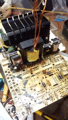
vb99
Good evening!
As I understand it the PSU goes into protection when a sudden change in current, both in voltage and in current limitation mode. Respectively to refer to the incorrect work of the CCA current will not work, because it works in constant voltage mode where OOS initially worked fine. And BP is the scheme how the scheme of protection made?
- Great grizzly Adams . Flashed a hunch about all this drivel.
Good evening BP Scheme is not, In principle, standard ATX .The duty room uc3843 .The power switches D209L. The power unit is not touched.
Removed all the secondary and it danced. Simple protection on two transistors .In General, a complete repetition constructii this article only counted the dividers to fit your needs.
Good evening!
As I understand it the PSU goes into protection when a sudden change in current, both in voltage and in current limitation mode. Respectively to refer to the incorrect work of the CCA current will not work, because it works in constant voltage mode where OOS initially worked fine. And BP is the scheme how the scheme of protection made?
Good evening Yes, I was reading this article and used it as the Bible. Eventually rebuilt OOS selection method. The load or an adjustable resistance 0 to 15 ohms 200W tried an old laptop in the chaotic regime the load 19V (max consumption 7A) But turns off in any mode at sharp throws of a current. Sharply loading current more than 2A impossible.
2uz
Good evening. Need your advice Redid the ATX PSU into an adjustable on your technique to 35V 10A.
TRANS rewound itself. Frequency 65 KHz . This works like a charm .ripple minimum (at voltage 20mV .current 250-300mV . ) The first thing that puzzled it took a slow OOS. RC circuit for voltage stabilization 43K and 0.033 µf current 68К and 0.1 UF. What can be the reason?
The second can't suppress a release with a sharp lifting powerful loads or connection. Fire protection (20A) Tried different choke and capacitance in the filter . to no avail. Probyval play with saberon on the Schottky diodes did not help . Maybe there are ways to suppress these emissions? Already 3months I have often wanted to send it in the trash)).
Good evening!
This is a good article with practical recommendations for setting up a compensation feedback
bsvi.ru/kompensaciya-obra...azi-prakticheskij-podxod/
Test circuit for output load power supply and the analysis of the response of the feedback I'm on the same TL494 on the breadboard did.
And, the same unit goes into protection in the voltage and in the constant current mode?
Strong release when the load is removed can also be due not only to incorrect operation of the circuits of feedback, as well as in the secondary circuits of the excessive inductance of long connecting wires, shunts. To that you the frequency of raised and ACC. these inductors will have a greater impact to provide.
There are of course an option to crush the integrator in the defense, but I think it's the latter it makes sense to do.
Two thousand three hundred fifty
Good evening! A lot depends on the mounting resistance of the power conductors, their length, etc. You raised the output voltage is, of course, much has changed.
But, the emissions can be related to the slow response of BP because of the inertia operating system. Of the causes can be several.
The more rapid the OSS voltage regulation works perfectly. But the stabilization of the current no. (whirring) Oscillum even sync can not . Or on certain modes visible pillsacai 10V and above.
Emission cuts BP in all strains . Whether it's a 1V Il 35V . I noticed that the fascination of the size and inductance of the inductor, the situation improved a bit Shook up to 470мкГн on the ring 39.9/24.1/14.5. Installation almost factory except for the transfer of all former line 5B . TL494 placed on a separate Board (as it was from the factory I only peirsol it to fit your needs) In principle, all items remained on the regular places.
The lines of force built up with solder.
Good evening! A lot depends on the mounting resistance of the power conductors, their length, etc. You raised the output voltage is, of course, much has changed.
But, the emissions can be related to the slow response of BP because of the inertia operating system. Of the causes can be several.
Good evening. Need your advice Redid the ATX PSU into an adjustable on your technique to 35V 10A.
TRANS rewound itself. Frequency 65 KHz . This works like a charm .ripple minimum (at voltage 20mV .current 250-300mV . ) The first thing that puzzled it took a slow OOS. RC circuit for voltage stabilization 43K and 0.033 µf current 68К and 0.1 UF. What can be the reason?
The second can't suppress a release with a sharp lifting powerful loads or connection. Fire protection (20A) Tried different choke and capacitance in the filter . to no avail. Probyval play with saberon on the Schottky diodes did not help . Maybe there are ways to suppress these emissions? Already 3months I have often wanted to send it in the trash)).
